• The move to the new server is done. There are some software and database maintenance updates in process. This has us passing the hat around to help out. We appreciate any donations. Seriously, even a dollar helps. The payment page may be found here - https://www.audiokarma.org/support.html

What were the engineers trying to accomplish in this circuit?

Sam Lysinger

Please support your local mad scientist
Subscriber
Greetings,

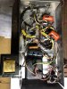
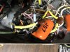
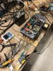
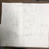
I've recently serviced a Sylvania console chassis for educational purposes as I've not wrenched on a stereo single ended amplifier like this one before. (And I cannot say no to adopting an ugly amp that is getting no love.) With no markings, I had to draw out a schematic to make sense of what is in there. I've attached the schematic (be kind, second time drawing one ^_^) and am curious to know:

Why is there a .001uf cap between the input taps of the output transformer?
Why is there an RC network of some sort between the cathode of the driver tube section and the power tube? (I'm not married to keeping it there, mainly curious why it is there in the first place as I've never seen something like this before, possibly for good reason)

Given the hum issues, I added the 40uf cap and 1.5H choke to quiet things down. It needed it pretty badly. The unit now sounds okay on 90db bookshelf speakers (but not so good on 97db EV duplex speakers), but I need to drop the screen voltage at least 40v and plan to work on that next.

All insights are greatly appreciated!
 

Attachments

  • IMG_3282.JPG
    IMG_3282.JPG
    81.9 KB · Views: 112
  • IMG_3283.JPG
    IMG_3283.JPG
    145 KB · Views: 100
  • IMG_3284.JPG
    IMG_3284.JPG
    110.2 KB · Views: 99
  • IMG_3285.JPG
    IMG_3285.JPG
    122.4 KB · Views: 100
  • IMG_3286.JPG
    IMG_3286.JPG
    94.1 KB · Views: 103
Register to hide this ad
The 0.001uF likely helps roll-off the treble response, and may also help to suppress any over-voltage transients if ever they occur.

The RCR circuit provides feedback of the output stage cathode to the input stage cathode, as both those cathodes are not capacitor bypassed. You could measure the level of feedback by lifting one end of the 47k.

It's difficult to see but I presume the original 40uF and 150uF supply filter caps are cans located on the other side of the chassis? Did you test those for capacitance and ESR, and for leakage current at their rated working voltage?

The input circuit's 5.2M is typically too high a value (eg. 100k to 470k depending on valve). Any input audio connection would need to be very well screened and connected to avoid hum - you can check that by adding a temporary wire link from pin 7 to 0V.
 
The 47k to the cathode isn't really providing much feedback, or possibly any honestly. The cap to ground mostly eliminates any signal there. It does provide a bit of fixed bias to the driver though. The unbypassed output tube cathode resistor is doing most of the feedback duty here.

Honestly I'd be real tempted to rework this to a more conventional se amp with global feedback. Goofy circuits are interesting but usually suited to a specific purpose which may not make them so useful in a general way.
 
The 0.001uF likely helps roll-off the treble response, and may also help to suppress any over-voltage transients if ever they occur.

The RCR circuit provides feedback of the output stage cathode to the input stage cathode, as both those cathodes are not capacitor bypassed. You could measure the level of feedback by lifting one end of the 47k.

It's difficult to see but I presume the original 40uF and 150uF supply filter caps are cans located on the other side of the chassis? Did you test those for capacitance and ESR, and for leakage current at their rated working voltage?

The input circuit's 5.2M is typically too high a value (eg. 100k to 470k depending on valve). Any input audio connection would need to be very well screened and connected to avoid hum - you can check that by adding a temporary wire link from pin 7 to 0V.

You are correct, the 40uf and 150uf were originally a can (of lesser values), but I cut that can off, drilled some holes and put those critters in place of them.

It's an 8.2M resistor at the input circuit, nearly 40 years of typing has done wonders for my handwriting, I can clip a 470K in parallel to the 8.2M and see what happens. It's probably time for me to denote that the driver tube is a 12AX7 on the schematic ^_^

Thanks!
 
Can you confirm the value of the RCR cap - the schematic indicates 1uF, but I can't easily see a 1uF cap in the photos.
 
The 47k to the cathode isn't really providing much feedback, or possibly any honestly. The cap to ground mostly eliminates any signal there. It does provide a bit of fixed bias to the driver though. The unbypassed output tube cathode resistor is doing most of the feedback duty here.

Without that cap to ground between the 2K and 47K resistors the feedback would be positive. Perhaps the value of that cap is low enough to still create some positive feedback at low frequencies.
 
^^ that was my conclusion also. Bass boost at 80 Hz and less, assuming schematic drawn correctly.
 
yeah, probably the case. Another situation of oddball engineering for a purpose that I think would just be better to eliminate entirely. Run a normal feedback loop off the speaker secondary, bypass the output tube cathode with a reasonably large cap, should do well to make it behave itself.

possibly also need a larger 12ax7 cathode resistor, with an 8.2M grid resistor its as much grid leak bias as anything else.
 
It's an 8.2M resistor at the input circuit
That's large enough to create grid leak bias. If you change this to a more typical value, you'll need to increase the value of the cathode resistor at the same time and eliminate the connection between the two cathodes. The output stage needs a bypass capacitor across the 300Ω cathode resistor, and the circuit needs NFB added to reduce the IM of the output stage to tolerable levels.

Jack
 
Ta, so appears to be some bass boost tone shaping (below 800Hz), given the interstage coupling and the OPT primary inductance would shelve and then drop that LF gain.
 
The 47k to the cathode isn't really providing much feedback, or possibly any honestly. The cap to ground mostly eliminates any signal there. It does provide a bit of fixed bias to the driver though. The unbypassed output tube cathode resistor is doing most of the feedback duty here.

Honestly I'd be real tempted to rework this to a more conventional se amp with global feedback. Goofy circuits are interesting but usually suited to a specific purpose which may not make them so useful in a general way.

Good info, thx! I'm not married to the current circuit whatsoever, nor the OPTs as the turn ratio is 49:1 making the load 19K with an 8ohm speaker attached. Is there a recommended 6v6 SE circuit? (One for a traditional OPT and one for an ultralinear OPT?)
 
Odds are it was originally driving either a 3.2Ω speaker or two 4Ω speakers in parallel in each channel, and with such a high input impedance, this was likely one of those many designs used in record players of the day that employed a crystal pickup, whose signal was first passed through a (remote) very high impedance passive tone/volume control circuit before being applied to the amplifier proper. The high input impedance would be needed to prevent loading such circuits down.

Dave
 
yeah 19k is sort of nuts. Datasheet conditions exist for class A 6v6 with either a 5k or 8.5k load depending on voltages and such.

as for what to do with it, that again depends on your available voltages and what transformer you want to use.

something like this ought to work though. No specific experience, just something I found on a general internet poke-around

Audio Data - 6V6 - 12AX7 Single form Japan (timf.net)

adapt your power supply as needed to get basically those voltages and stick a 5k to 8 ohm output transformer in there. You can also skip the input volume control if you want, just sub a 470k to ground at the grid. Possible this will want some fine tuning to get the feedback just so but this ought to give a reasonable starting point.
 
yeah 19k is sort of nuts. Datasheet conditions exist for class A 6v6 with either a 5k or 8.5k load depending on voltages and such.

as for what to do with it, that again depends on your available voltages and what transformer you want to use.

something like this ought to work though. No specific experience, just something I found on a general internet poke-around

Audio Data - 6V6 - 12AX7 Single form Japan (timf.net)

adapt your power supply as needed to get basically those voltages and stick a 5k to 8 ohm output transformer in there. You can also skip the input volume control if you want, just sub a 470k to ground at the grid. Possible this will want some fine tuning to get the feedback just so but this ought to give a reasonable starting point.

Thank you for the point in the right direction! I solved my high plate and screen voltage issues by converting the power supply to a choke input. If I happen to need more voltage, I can replace the 6ca7 with diodes. With the 1.5H choke the hum was very high, so I jumpered in a 12H choke and things are quieter (460mv ripple down to 22mv at the second capacitor). I may add a resonator to the choke to see how much better the ripple improves. I also found a box of Stromberg Carlson TR-30 12W 70v transformers and jumpered one in after computing a 5K to 8 ohm turn ratio. It delivers less power than the 19K transformer, but it sounds noticeably better. Less distortion, more detail, better treble (on the sacrificial test speakers anyway). The next step is to cut out all the cathode feedback junk and replace the 8.2M resistors with 470Ks as recommended. Once that is listened to a bit, I am considering an ultralinear arrangement to see what happens (maybe something good, maybe something bad...) Then it will be on to rewiring this little mudpuppy to look even more like the link you sent me.
 

Attachments

  • TR-30turnratios.JPG
    TR-30turnratios.JPG
    34.5 KB · Views: 5
  • IMG_3387.JPG
    IMG_3387.JPG
    168 KB · Views: 5
are those transformers meant to handle DC on the primary? If not its probably saturating and limiting your power output.
 
are those transformers meant to handle DC on the primary? If not its probably saturating and limiting your power output.
I'll be you money they are not ^_^ They are 70V to 8ohm. I wanted to get something in place I had on-hand before ponying up for some Edcor or Japanese iron. Despite the lack of power, they are an improvement. Thanks again!
 
Fair enough. I have something I need to fork over a couple dollars for and haven't so far. Parts are under 50 but spending money and having to wait for what I paid for just isn't exciting
 
Back
Top Bottom