• The move to the new server is done. There are some software and database maintenance updates in process. This has us passing the hat around to help out. We appreciate any donations. Seriously, even a dollar helps. The payment page may be found here - https://www.audiokarma.org/support.html

Where to measure cathode bias current...Fisher X-101B

Aberbs1

Member
This may be a stupid question, but for a cathode biased amp (Fisher X101-B), across which resistor can I measure bias current? The Aikenamps website states....

"Checking the bias current in a cathode biased amplifier is easy, just measure the voltage across the cathode resistor and divide by the resistance value to obtain the cathode current."

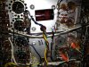
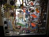
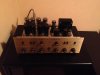
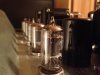
I've attached some pics and the schematic below. Is he talking about measuring the two green 7 watts resistors going to ground? ...or across the variable resistor (bias pot), or one of the resistors attached to it...? Also, I've read that this particular bias circuit supplies DC to 4 of the 12ax7's heaters (which act as cathode resistors). How would I account for this if I wanted to find the cathode current going to the output tubes?

I've adjusted the bias to 44v at pin 5 of the 7591's as per the service manual. I'm getting 441v at the plates and 407v at the screen grids. The cathodes are tied together, as are the screen grids. I'm using a matched quad of EH 7591's. I just want to make sure I'm operating these tubes within their dissipation limits, but I'm at a loss for how/where to measure current in this particular circuit. Any guidance would be much appreciated!
Adam
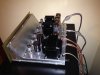
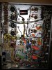
IMG_1162.jpg

IMG_1140.jpg

View attachment X-101-B p1.pdf

View attachment X-101-B p2.pdf

View attachment X-101-B p3.pdf

View attachment X-101-B Parts List1.pdf
 
Register to hide this ad
Adam,
I know exactly what you mean.
I've read lots of technical information that assumes I understand what the author's talking about and he's just putting out a reminder.

Your work looks very good, though I'd love to see a picture of the front panel also.

What cathode bias does is treat the tubes gently and because of its design, the individual bias of the output tubes was looked upon as an afterthought, particularly when you could get new tubes locally.

If you do what the manual says, you will be within operating specs of the tubes.
As an alternative, you can capture the bias of each tube, but it's a judgement call as to whether it's worth it to you or not.
What I'd do, and this is just me, is put a 10 ohm resistor on the cathode of each 7591 in series with the single resistor. Then you can measure each tube. Since there's a resistor or resistors for the sum of the four outputs, just measuring across the plus and minus of each 10 ohm resistor with respect to ground will tell you how each tube is doing compared to the others. Swapping tubes in different sockets can give you two push-pull pairs that more closely match each other.
If you read this reference, just be aware that the cathode pin# changes from tube type to tube type.
http://www.audiokarma.org/forums/showpost.php?p=6008331&postcount=20

Hope this helps.
 
Last edited:
There is no single cathode resistance device on fisher amps of this design. The cathode resistance is a combined sum of a few resistors, the bias adjust pot and the heater filaments of the 12AX7's. When you set the voltage to 44V you have adjusted the amp properly and you are done.
 
Last edited:
Great thanks guys...It's a relief knowing that I can stop fussing with this amp and get back to enjoying it:) While the cathode bias circuit might lack the flexibility of some other fixed bias circuits, the added "safety net" it provides the tubes is comforting (so long as the amp is in good working order). I might consider installing individual cathode resistors in the future, but for now it seems that the matched quad of EH 7591's I got from PartsExpress are stable and strong.
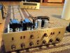
This really is a sweet sounding amp. It has surprising headroom for its 40 wpc spec, even when mated with somewhat power hungry speakers (NHT 2.9's). The recap was time consuming but not overly tedious; unlike my Sansui AU-70 which was kind of a nightmare at times. The only thing that was a PIA on the Fisher was getting those original can caps desoldered and detached from the chassis.

Another quick thought regarding cathode vs fixed bias... Given today's line voltages, biasing a fixed bias amp a little cooler than spec has obvious merits. Does the same hold true for a cathode biased amp? I wonder what the effect would be of setting pin 5 on my X101-B to say 40v (instead of 44v). My understanding is that the amp will "self-adjust" during operation anyways, so is there any point to lowering the bias? Btw, the X-101B does have a single "bias adjust" pot. Anyways, sorry for the long post...thanks again for your help!
Adam

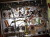
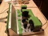
Here's a couple more pre/post recap pics...
IMG_0521.jpg

IMG_0528.jpg

IMG_0599.jpg

IMG_1185.jpg

IMG_0704.jpg
 
If you were to bias it today to 44v, you would be doing that to today's higher AC voltages, right?
If you'd like to do something for your amp, I'd suggest getting a pair of CL-80 thermisters and putting one on each side of the power supply's primary windings (the two black leads). That will drop the voltage to the primary a bit, provide a soft start and take the sparc arc risk away from the on/off switch.

That paper covered cap should be replaced with a modern electrolytic also.

Additionally, these are notorious for being hard on the power supply transformers, so putting in the thermisters and (1/4 or 1/2 watt resistors) sooner rather than later might be a good move. It's cheap insurance anyway.
Best of luck on a beautiful unit.
 
Last edited:
Adam -- you would not want to set the bias voltage any lower than 44 volts on this particular amp. This amplifier was carefully designed so that the 44 volts at the output tube cathodes not only biases the output stages correctly, but also provides just enough voltage to power the heaters of the phono preamp and the line/tone amp small signal tubes. These tubes (12AX7s) are designed to have their heaters operate on 12.6 volts. With Fisher wiring the heaters of these tubes in series then, you can see that with 44 volts applied to the heater string, each tube is only getting about 11 volts to its heater. That voltage level is sufficient to operate the tubes, and even has benefits in reduced noise by operating them at a lower heater voltage. But to operate them at 10 volts (which a 40 volt bias voltage would produce per tube) would cause an excessively long warm up time, and also likely degrade the performance of these stages significantly. Therefore, it is best to leave the bias set at 44 vdc with the stock design. The purpose of connecting the heaters of these tubes in the cathode circuit of the output stage is to operate them from a DC source of voltage rather than an AC one. While the technique does make for a bit of a screwy output tube bias arrangement, it does lower noise in the earlier stages quite dramatically.

Because of all of this, if you want to add individual biasing controls for each output tube, it can be done, but will need to be thought out very carefully so as to not compromise the required current flow necessary to power the heater string. With this understanding then, any effort to reduce quiescent current flow through the output stage will begin with providing an alternate source of DC power for the heater string circuit currently connected there.

This topic has received much discussion over on the Fisher Forum, so you might want to check that site out as well.

I hope this helps!

Dave
 
I never cared for these types of designs. Unnecessarily complicated and too fragile IMO.

IMHO they are really not all that complicated and are pretty darn reliable. I'd never design a circuit like this but they do work well. This design decision was strictly a dollar and sense move by Fisher. The more expensive amplifiers in their line were all fixed adjustable bias like the X-202B. I'd rather see this design where DC is heating the front end and phono section tubes then EICO's way of cost saving of heating them with AC.

Scott did the same type of cost cutting measures in the 200 and early 222A/B series of amps.

As a general rule cathode biased amplifier have a more relax sound
 
Thanks again guys. I really do appreciate the help.

Audiodon - I probably should have labelled the individual photos "pre" or "post" recap. They're kind of mixed. That Minimite paper covered cap is long gone...replaced with the JJ seen in my first post above. I like the thermister idea...was also considering running off a variac.

Dave - Thanks again, that was exactly the clarification that I needed. I'll leave it at 44V.

NOS - I agree 100% about the "relaxed" sound. I've always been able to listen to this amp for hours without fatigue.
Adam
 
It might be a good idea to install the 10 ohm resistors on the 7591 cathodes, just to see where you are at current wise, and for a little piece of mind.

I restored my X 101 B about five years ago. Restored, bias at 44V, amp running on todays AC wall voltages, my amps output tubes were drawing over 50ma each.

I had some problems with my bias circuit, quite a few kind AK members gave me some really good tip and pointers to get things squared away. If you do a search in the Fisher forum you can find the treads.

I run my X 101 b from a variac et at 115 volts. This brings the voltages right at schematic values. Even with the variac my EH 7591's are drawing 40ma each. I bought my EH 7591's from Jim McShane, he told me 40ma would be ok. They have ran this way for a few hundred hours now with no problem. Jim told me Fisher designed the 101 B to run the tubes hard. I guess it wasn't a problem when new 7591's were a buck each.

You have a really nice looking amp.
Hope you enjoy yours as much as I have.
 
Hello there,
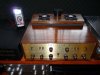
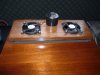
I have just finished restoring my Fisher X101B after investing around US$400 for a replacement PT from Heyboer, a OPT from Transcendar, a good used Westinghouse 7591, couple of JJ electrolytics and other odds and sods. The amp. is running very hot. One of the old Fisher 7591 is making noise while warming up and after 20 minutes of playing, the bias voltage has creeping up from 44V to 55V and I can see its PP partner has a red plate. So I suspect that the tube may have a short. Sure enough, problem is gone with the replacement tube. I worry so much about the bias voltage creeping up, I always connect a voltage meter to monitor. I set it at around 42.5 ~ 43.5 v. and it works and sounds great. The replacement Heyboer transformer is getting hotter than other amps. I have. After 2 hours of playing, it is up to 146 deg.F. and the OPT is 132 deg.F. These figures are out of my comfort zone. So I rigged up a cooling system using 2 computer fans mounted on a piece of 3/4" thick pine board with 1/2"x1/2" closed cell foam strip to act as damper so the vibration will not transfer to the tubes.They are fed by a tiny 12v transformer, a diode and a filter cap. It is plugged into the socket in the amp., so whenever the amp. is on the cooling fans will be on.
Now the temperature of the PT is down from 146 F to 109 F. The bias is constantly between 42.5 ~ 43.5 v. An AC amp. meter connected in the input line shows the amp. draws 1.2 Amp AC. I have also decrease the 3.2 Amp Slow Blow fuse to 2.5 Amp. for added protection. I don't know if I am running my amp. correctly within these parameters so that I can have the peace of mind to play her for longer time. This is a very nice sounding tube amp.
Your comments welcome.
Ken
Vancouver, BC
 
Back
Top Bottom