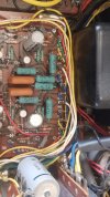
I've just finished recapping a fine little Kenwood KA-4002 integrated amp and I'd like to adjust the bias. There are two trimpots on the main amp portion of the one an only board in this unit and the generic Kenwood bias adjustment guide link indeed listed the KA-4002 and a bias to shoot for even though the KA-4002 service manual doesn't cover it.
Normally, I'd just follow the schematic and measure voltage across the final output transistor's emitter resistor... but there are more than one in this unit (to my wholly untrained eye). So, which one (or more) of these resistors should I be measuring across as I adjust trimpot VRe1? And please help explain why you pointed out the ones you did so your advice might be applied to others (i.e. me when I'm working on the next little gem) as they do something similar in a different unit.
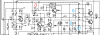
If I was taking a wild guess, I'd say I should measure from the "top" side (as per diagram) of Re91 (since that looks like the emitter on Q1) all the way through to the "top" side of Re 93 (since that looks like the emitter on Q2), but there is cap Ce59 in the path between those and that makes me think that can't possibly be right. Help!
(Image below is just one half of the schematic, just one channel)
Thanks!
Normally, I'd just follow the schematic and measure voltage across the final output transistor's emitter resistor... but there are more than one in this unit (to my wholly untrained eye). So, which one (or more) of these resistors should I be measuring across as I adjust trimpot VRe1? And please help explain why you pointed out the ones you did so your advice might be applied to others (i.e. me when I'm working on the next little gem) as they do something similar in a different unit.
If I was taking a wild guess, I'd say I should measure from the "top" side (as per diagram) of Re91 (since that looks like the emitter on Q1) all the way through to the "top" side of Re 93 (since that looks like the emitter on Q2), but there is cap Ce59 in the path between those and that makes me think that can't possibly be right. Help!
(Image below is just one half of the schematic, just one channel)
Thanks!