• The move to the new server is done. There are some software and database maintenance updates in process. This has us passing the hat around to help out. We appreciate any donations. Seriously, even a dollar helps. The payment page may be found here - https://www.audiokarma.org/support.html

Why are there resistors in SPEAKER SELECTOR?

SamiK

New Member
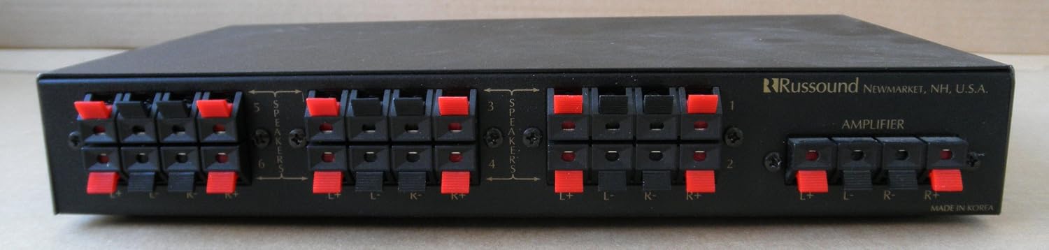
I just bought this Russound 6 channel speaker selector. On the faceplate, it says, Impedence matching, 6 pair speaker selector.
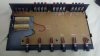
Being the curious fellow I am, I opened the unit to see what was inside.
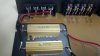
I was expecting to see bunch of wires to make speaker selection possible, but I also saw two resistors. They were 50W 3Ohm 5%. Why are these necessary? Are these necessary for "impedence matching?"
I plan to use it just as speaker selector. I plan to use 3 or 4 pairs of speakers in my livingroom, and I want the conveniece of being able to switch from one set of speakers to another, so that I can enjoy music on different set of speakers. I am not trying to do anything fancy.

Can I just take these resistors out of circuit?
 

Attachments

  • 2017-01-18_13-22-41_654.jpg
    2017-01-18_13-22-41_654.jpg
    65.2 KB · Views: 98
  • 2017-01-18_13-22-52_104.jpg
    2017-01-18_13-22-52_104.jpg
    52.6 KB · Views: 98
Register to hide this ad
That is the exact model. There is no impedence matching button anywhere. So, the resistors are always in circuit.
I won't be needing impedence matching function, so can I remove it?
 
No need to remove the resistors. Just run it in "Bypass" mode and it should bypass the resistors. A word of warning. The resistors are in there to keep from overloading your amplifier. Every set (pair) of speakers that you have switched "on" are wired in parallel with each other. So if you have two sets of 8 ohm speakers switched on at the same time, you are basically presenting a 4 ohm load to the amplifier. The more sets of speakers you have switched on at the same time, the lower your impedance presented to the amplifier. If you have all six sets of 8 ohm speakers "on" at the same time, you are presenting a load of approximately 1.3 ohms. In this situation, the resistors (3 ohm) will be wired in series with the 1.3 ohm load of the speakers. 3 + 1.3 = 4.3 ohms. What these resistors are doing is ensuring you have at least a 4 ohm load on the amplifier at all times to prevent amplifier overload and potential damage to the power output transistors (impedance matching mode). If you are only planning to run a single set of speakers at a time, you can safely use the switch in "Bypass" mode. Otherwise, you will need to do a simple calculation to determine the load that will be presented to the amplifier when running multiple sets of speakers simultaneously.

Did this help? There are numerous parallel resistance calculators on the web. Keep in mind, these calculations are for DC resistance values. Actual speakers have an impedance which varies with frequency.
 
Last edited:
That is the exact model. There is no impedence matching button anywhere. So, the resistors are always in circuit.
I won't be needing impedence matching function, so can I remove it?
If that's truly the same model, the switch is found on the rear.

I cannot imagine why they would be there if not for the purpose described.
 
That is the exact model. There is no impedence matching button anywhere. So, the resistors are always in circuit.
I won't be needing impedence matching function, so can I remove it?
If it is the model SS-6.2, there should be switch on the back labeled "In" and "Bypass". The "Bypass" mode bypasses the resistors. There is no need to remove the resistors.
 
The SS 6 (as opposed to SS 6.2) model does not appear to have the bypass function.

Russound's website claims the impedance function is "automatic" on the SS 6.

71oWDcKuy9L._SL1500_.jpg
 
Thank you Decibel_116.
I now understand why it's there. I guess my unit is SS-2. So, the impedence matching is done automatically.
I would be using one pair at a time. So, I won't be needing the impedence matching function. Could there be any harm in removing them? My reasoning is that simpler the circuit, less there is to corrupt the performance.
 
My reasoning is that simpler the circuit, less there is to corrupt the performance.
That is true, removing the switching device itself will reduce whatever "performance corruption" that it adds to the equation. It's all about compromises, those you're okay with and those you are not.
 
I'm not clear on how it is done 'automatically' in your version of the unit. Presumably the resistors are switched in whenever two or more pairs of speakers are on at the same time. If you won't be doing that, they will not be in the circuit, nor will any switch contacts they are connected to. [EDIT: The above appears to be incorrect - see the next two posts.]

If you remove them, at least tape a note to the bottom of the unit to remind yourself and future owners that they were removed, so someone doesn't try to use it with multiple speakers thinking it has impedance matching.
 
Last edited:
If that picture and the rear panel pic are correct, it has the resistors in series regardless of the combinations you set. It is to protect their ass, not yours as there never can be an impedance lower than 3 ohms (your amp won't explode). As you switch in more and more parallel connected speakers, the drop across the 3ohm resistor increases and more power is lost in those 50 watt aluminium cans.

I would scrap the entire switcher- it is a damping factor killer and poorly designed.
 
Hey you're right - I didn't look at the pics in the original post close enough - it looks like the resistors are in series with the outputs and everything goes through them no matter what. I'd take them out of the circuit as long as you are careful to manage your switching. If you wanted to get fancy you could add your own switch to switch them in when you have multiple speakers running, if you think you'll ever do that.
 
OTOH, some people like a few ohms in series with the speakers to reduce damping and fatten up the sound.
 
Be careful, those are only 50 watt resistors.

I picked up a Niles that had a fried resistor in it.

Rob
 
Describe 'fatten'-ing please, I have not heard of this effect.

OK, I'll take a swing at this. Most drivers have an impedance curve. One that has a hump at the resonance point and an up sloping curve as the frequency goes higher. The lowest impedance is usually in the midrange. When you put a resistor in series with the driver, the resistor cuts out more signal at the drivers low impedance point. SDFR speakers can really benefit from this and my current FR 8 ohm speakers have a 4 ohm resistor in series with them.
 
Actually, now you come to mention it...I see an opportunity for the latest magic tweak box- switchable series resistances to tailor the sound using sand-cast high quality nichrome resistors to fatten up your bottom end and smooth out the midrange, etc.
 
Pretty sure the resistors only come into play to reduce transients as you operate the switch, so we're only talking a millisecond load ...
 
If you're still bound and determined to remove those resistors, and since you say they are "in line" with eveerything, then you might be better off simply bypassing then with jumpers instead of removing them.

Then, if/when you realize why they are there, their functionality can easily be restored.
 
There is no perfect way to combine multiple speakers to a single amplifier without compromising the system in most cases. There were a few Mcintosh amps with 1 ohm outputs that could drive multiple speakers with out compromises. But speaker boxes are always a compromise unless load resistors are removed and the switches are more than capable of carrying the total current of the amplifier.
 
Back
Top Bottom