• The move to the new server is done. There are some software and database maintenance updates in process. This has us passing the hat around to help out. We appreciate any donations. Seriously, even a dollar helps. The payment page may be found here - https://www.audiokarma.org/support.html

Why Does 2325 Amp Have Full Voltage Readings W/O PWR Supply?

richardg0n

Active Member
I am troubleshooting a possible short on one of the 2325 amps connected to a DBT and only having one amp in the receiver. I have the RCA connected to the amp only.

Can someone explain why I can take full voltage readings with my multimeter on the components without the amp power ribbon connected? Doesn't the amp need the power ribbon connected to power the amp?
 
Register to hide this ad
Probably because there's no ground reference with the connector off, ohm it out with power off. Why the heck would you take voltage readings on a board with no power connected?
 
What do you mean by "I have the RCA connected to the amp only."?
  • Only one P700 installed in the chassis, other side is completely removed and disconnected from chassis wiring?
  • Only J701 connected to wiring harness of installed board of something else? What is connected to the Main In RCA jack?
  • J710 is disconnected from wiring harness of installed board?
  • Chassis is powered ON with a DBT?
  • Where are you measuring "full voltage" at, and with reference to chassis ground or something else?
 
What do you mean by "I have the RCA connected to the amp only."?
  • Only one P700 installed in the chassis, other side is completely removed and disconnected from chassis wiring?
  • Only J701 connected to wiring harness of installed board of something else? What is connected to the Main In RCA jack?
  • J710 is disconnected from wiring harness of installed board?
  • Chassis is powered ON with a DBT?
  • Where are you measuring "full voltage" at, and with reference to chassis ground or something else?
  • Only one P700 installed in the chassis, other side is completely removed and disconnected from chassis wiring? - Yes

  • Only J701 connected to wiring harness of installed board of something else? - RCA connected to J701

  • What is connected to the Main In RCA jack? - The RCA cable coming from MAIN / PRE in the back of the unit.

  • J710 is disconnected from wiring harness of installed board? - Yes, J710 is not connected to wiring harness. The Power supply relay will not come out of protection when the wiring harness is connected to J710. The power relay does come out of protection only when the RCA is connected to J701.

  • Chassis is powered ON with a DBT? - Yes

  • Where are you measuring "full voltage" at, and with reference to chassis ground or something else? - I am measuring the full voltage on various components ground to chassis (mostly around 29VDC).

    I am getting full voltage readings with ground connected to the chassis and without the wiring harness connected to J710. Does the RCA connection at J701 also provide full voltage to the P700 board. I was not expecting any voltage readings when powered on a DBT. My understanding is that the RCA connection is needed for grounding when J710.
 
Let's recap what I think you said (sorry, but I want to get this right):
  1. With no cables attached to the P700 board the power relay will click.
  2. When you attach ONLY the RCA cable to J701 (and not J710), the power relay does not click and you measure a voltage of 29VDC at various points on the P700 board.
  3. With J701 unplugged from the P700 and with it turned-on, measure the DC voltage on the cable that goes to J701 from the RCA center conductor to outer conductor (shield).
  4. The next thing to try is to connect the bad P700 to the other (good) channel to see if it works OK. If it does, then there is something else wrong.
  5. My thought was that you are actually getting DC leakage from the output of the Pre-amp for the bad channel and it is not the P700 Main Amp board that is bad.
 
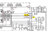
It's still nagging me (see post #2) that both connectors need to be on for even a good unit to operate. Looking at the schematic, they show that the RCA shield is earth/chassis grounded to the left of the per out/main in jack panel. Then at the board, the 4-pin connector is also shown as earth ground. But look at the right of the schematic at the heavy line, presumably ground by line weight and the way it connects. It's floating! Maybe it should've been shown connected to the 4-pin connection and if so, is floating and NOT grounded which may show weird floating voltages.

Simple test is to leave all unplugged or just measure the loose module and do a resistance check between the RCA jack shield and the middle of the 3 closer spaced pins on the 4 pin connector pins. That should correspond to the black wire on the socket wired into the chassis. If it's open, my theory is correct, and you'd have to clip on a jumper to make that ground connection with the 4-pin unplugged.
 
Let's recap what I think you said (sorry, but I want to get this right):
  1. With no cables attached to the P700 board the power relay will click.
  2. When you attach ONLY the RCA cable to J701 (and not J710), the power relay does not click and you measure a voltage of 29VDC at various points on the P700 board.
  3. With J701 unplugged from the P700 and with it turned-on, measure the DC voltage on the cable that goes to J701 from the RCA center conductor to outer conductor (shield).
  4. The next thing to try is to connect the bad P700 to the other (good) channel to see if it works OK. If it does, then there is something else wrong.
  5. My thought was that you are actually getting DC leakage from the output of the Pre-amp for the bad channel and it is not the P700 Main Amp board that is bad.
  1. With no cables attached to the P700 board the power relay will click. - Yes

  2. When you attach ONLY the RCA cable to J701 (and not J710), the power relay does not click and you measure a voltage of 29VDC at various points on the P700 board.
    With only RCA attached to J701, The relay does click, and I am measuring 29VDC at various points on the P700 board.

  3. With J701 unplugged from the P700 and with it turned-on, measure the DC voltage on the cable that goes to J701 from the RCA center conductor to outer conductor (shield).

    Measured DC voltage on RCA cable, outer conductor 30VDC, center conductor 29VDC.

  4. The next thing to try is to connect the bad P700 to the other (good) channel to see if it works OK. If it does, then there is something else wrong.

    I moved P700 to the other side and am getting the same results.

  5. My thought was that you are actually getting DC leakage from the output of the Pre-amp for the bad channel, and it is not the P700 Main Amp board that is bad.

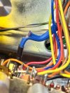
    I had to replace a severed wire from PU01 to the PRE/MAIN RCA. I thought the wire replacement could be the cause of the unwanted DC leakage, but I am not convinced this is the culprit. I going to check the voltage reading on PU01 and will report back.


    IMG_0762 2.jpg
 

Attachments

  • IMG_0764.jpg
    IMG_0764.jpg
    149.8 KB · Views: 2
  • IMG_0802.jpg
    IMG_0802.jpg
    171.8 KB · Views: 2
  • IMG_0980.jpg
    IMG_0980.jpg
    127.5 KB · Views: 2
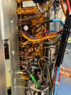
I followed the full voltage readings back to PU01. I documented the resistor and transistor voltage readings. A few resistors need to be replaced because of the peeling of the external casings, but I did not see any resistors that looked damaged or burned. I previously replaced the CAPS and transistors on this board for this restoration.
 

Attachments

Looking at your schematic, your voltage measurement of JU08 doesn't look right.
JU08 is tied to chassis ground but measures 30VDC?? Where did you have the DMM black lead.. on the chassis?
1708579723042.png
 
JU08 should be 0VDC with respect to the chassis, not 30VDC. Is there a wire on JU08 that is tied to the chassis, typically a black wire. Maybe you forgot to reconnect a lug to a ground screw on the chassis when you removed the board? You can test this with POWER OFF and UNPLUGGED, put your DMM into ohms and measure the resistance from JU08 to chassis ground. What do you get?

JU04, you measured at 0v which is correct so the chassis ground is not the problem. It has something to do with JU08?

You also have a huge DC voltage on JU06 & JU07. That shouldn't be there also.

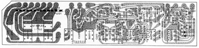
Carefully examine the solder pads on the PU01 board for solder shorts. If you post a good photo of the top and bottom sides of the board so I can also look at it. Compare it to the layout below. Follow the ground trace JU08 through its path and make sure there are no solder blobs connecting to another trace.
1708585006164.png
Where exactly is this wire coming from/going to and how did you repair it?
1708582549460.png
Also, you said in a previous post that you replaced transistors on this board. What transistors did you use to replace HU05, HU06, HU07, HU08?
 
Last edited:
JU08 should be 0VDC with respect to the chassis, not 30VDC. Is there a wire on JU08 that is tied to the chassis, typically a black wire. Maybe you forgot to reconnect a lug to a ground screw on the chassis when you removed the board? You can test this with POWER OFF and UNPLUGGED, put your DMM into ohms and measure the resistance from JU08 to chassis ground. What do you get?

JU04, you measured at 0v which is correct so the chassis ground is not the problem. It has something to do with JU08?

You also have a huge DC voltage on JU06 & JU07. That shouldn't be there also.

Carefully examine the solder pads on the PU01 board for solder shorts. If you post a good photo of the top and bottom sides of the board so I can also look at it. Compare it to the layout below. Follow the ground trace JU08 through its path and make sure there are no solder blobs connecting to another trace.
View attachment 3126702
Where exactly is this wire coming from/going to and how did you repair it?
View attachment 3126696
Also, you said in a previous post that you replaced transistors on this board. What transistors did you use to replace HU05, HU06, HU07, HU08?
JU08 should be 0VDC with respect to the chassis, not 30VDC. Is there a wire on JU08 that is tied to the chassis, typically a black wire. Maybe you forgot to reconnect a lug to a ground screw on the chassis when you removed the board? You can test this with POWER OFF and UNPLUGGED, put your DMM into ohms and measure the resistance from JU08 to chassis ground. What do you get?

SOLVED!
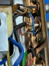
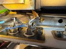
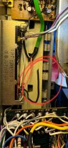
I was able to locate a broken ground wire that led back to JU08. I ran From JU08 to the crossfader and between the crossfader and ground near the P400 Phono stage. I replaced the broken ground wire and high voltage readings at 0VDC at JU08, JU06, and 3.5mv at JU07.

IMG_0998.jpg
JU04, you measured at 0v which is correct so the chassis ground is not the problem. It has something to do with JU08?

Yes.

You also have a huge DC voltage on JU06 & JU07. That shouldn't be there also.

Carefully examine the solder pads on the PU01 board for solder shorts. If you post a good photo of the top and bottom sides of the board so I can also look at it. Compare it to the layout below. Follow the ground trace JU08 through its path and make sure there are no solder blobs connecting to another trace.

Where exactly is this wire coming from/going to and how did you repair it?

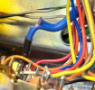
The blue severed wire was replaced with a shielded three-conductor wire that connects from PU01 to PRE OUT RCAs. I checked for voltage readings on the PRE/MAIN out and found 0VDC.
 
Back
Top Bottom