• The move to the new server is done. There are some software and database maintenance updates in process. This has us passing the hat around to help out. We appreciate any donations. Seriously, even a dollar helps. The payment page may be found here - https://www.audiokarma.org/support.html

Why Does the 2325 Power Supply Relay Function Only When Amp-Free

richardg0n

Active Member
Greeting AK,

Looking for troubleshooting advice. Restoring another 2325, and after recapping PS, the relay on PS will not open/click when the amps are connected(powered and RCA connected).

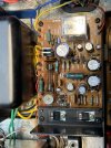
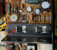
PS, amps, Pre, and PU01 have been recapped(see pics). Here is the sequence of steps I have taken to troubleshoot. I am using a DBT, which lights up initially, then dims to the point that the bulb looks off and the relay is not clicking.

1. I checked all the solder points on the PS and amps. Also, as a reference, I compared the solder tracks and points with another primarily original, unmodified amp, P700. Everything looks good.

2. I connected a third amp from another 2325, and there was still no change on the relay.

3. Measured output on P800 J808 and J809, expecting 100mv and got around 6vdc.

4. Checked the output at J804 and J805, and it's 35VDC when not plugged into the DBT.

5. Check all the resistors on P800 and replace a few because they were not to spec.

Advice is much appreciated.
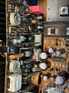
IMG_0805.jpegIMG_0804.jpegIMG_0756.jpeg
 
Last edited:
Register to hide this ad
Make sure you have the RCA input audio connector also plugged in. It provides a ground reference. I think! It does on a 2275.
 
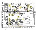
Voltage and resistance measurements on PS and Right Amp. Maybe you can see something I can't. See attached.


P800 measurements without DBT
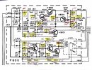
2325 schematic P800.jpg
 
Last edited:
Did the 2325 come out of protection with the power amps fully connected before you re-capped the PS board?
 
Did the 2325 come out of protection with the power amps fully connected before you re-capped the PS board?
I could not test it before the PS recap because of the condition. This 2325 looked like it was left outside and had thick dirt on the boards and some rust on the chassis. I always prefer to recap the PS and then test on DBT. It has worked in the past for me to eliminate issues with the current to the rest of the components in my restoration projects.
 
Thanks for the reply, the PS board is always the first one I restore in the 2275's and 2325's that I have restored.
 
Does it come out of protection when only one amp is all plugged in, and the other all unplugged? Then the other amp plugged in and the first one unplugged?

In the fault condition, measure the dc voltage on both main filter caps and the common ground between them, black/negative lead connected to the chassis somewhere other than the main filter cap common ground.
 
Does it come out of protection when only one amp is all plugged in, and the other all unplugged? Then the other amp plugged in and the first one unplugged?

In the fault condition, measure the dc voltage on both main filter caps and the common ground between them, black/negative lead connected to the chassis somewhere other than the main filter cap common ground.
2325 does not come out of protection when left and/or right power is plugged in. It does come out of protection when power is unplugged and RCA connected to amps.

I measured the DC offset voltage on both amps
and had confusing results using my multimeter measuring 702 and 708. I tried adjusting the results and had no movement in the voltage.

Right amp - 0 mv
Left amp - 192mv


Measured main caps
Front cap - -0.7
Rear cap - +0.7
 

Attachments

  • IMG_0820.jpeg
    IMG_0820.jpeg
    184.1 KB · Views: 3
Last edited:
Is the battery in the meter good? Anyway, the left amp output of 192mV shouldn't keep the relay from operating. Those main filter cap voltages are WAY low, maybe the meter lead on the chassis wasn't making good contact? Try using the common connection on the big caps for your ground. What I was trying to see before was the quality of that common ground between caps.

That's just weird that either amp being plugged in causes the fault condition.

On the marked up schematic it looks like the resistors in the relay circuit were measured but no voltage readings were taken. I'd look at H805 base, should be near zero. H805 collector at 1.2V. That would mean the relay driver transistors' base to emitter junctions should be good and the common collectors should be at 0.7Vdc and be turning the relay on.

That is as long as power is getting to the high side of the relay coil / H812 cathode end. R817 should be dropping the approx. 40Vdc down to 24Vdc if current is flowing through the relay coil.
 
Is the battery in the meter good? Anyway, the left amp output of 192mV shouldn't keep the relay from operating. Those main filter cap voltages are WAY low, maybe the meter lead on the chassis wasn't making good contact? Try using the common connection on the big caps for your ground. What I was trying to see before was the quality of that common ground between caps.

That's just weird that either amp being plugged in causes the fault condition.

On the marked up schematic it looks like the resistors in the relay circuit were measured but no voltage readings were taken. I'd look at H805 base, should be near zero. H805 collector at 1.2V. That would mean the relay driver transistors' base to emitter junctions should be good and the common collectors should be at 0.7Vdc and be turning the relay on.

That is as long as power is getting to the high side of the relay coil / H812 cathode end. R817 should be dropping the approx. 40Vdc down to 24Vdc if current is flowing through the relay coil.

I switched out the meter leads to alligator clips type, and the reading improved to 56v.

I measured voltages on all the resistors, including H805 Base and Collector, and measurements were within specification.

I measured R817, and the readings appear to be in the range you specified. See updated readings on the schematic below.

p800 measurments 2325.jpg
 
Bad relay? You measured 26.3v (27 - 0.675v) across the relay... so the relay should be pulling in? Or maybe bad solder connections to the PCB on the coil pins? You can measure DCV on the pins on the back side of the board to see if you get 26v.
 
Was this with an amp plugged in? If not, the relay should be operating, "clicked on" as it is. If one/both amps were plugged in, follow the advice of @dankik.
 
Bad relay? You measured 26.3v (27 - 0.675v) across the relay... so the relay should be pulling in? Or maybe bad solder connections to the PCB on the coil pins? You can measure DCV on the pins on the back side of the board to see if you get 26v.

The relay is new, but double-check the solder and measure DCV per your recommendation. Measured 27.66 - 0.691 when RCA's are connected and power to amps is not connected. There is no reading when the Left amp is connected. The right amp was not connected to access the bottom of the P800 power supply PCB.
 
Well then, maybe both amps are bad then. Weird but could happen. Maybe someone tried paralleling the speaker outputs and blew both. I'd offer to look at them but don't have a 2325 here to plug the amp modules in. You didn't say in the first post that it worked before you rebuilt the supply.

If it DID work before, plug in one amp and report the voltage on J808 and J809, they should be the same with either amp unplugged. Are you still getting 40 plus volts at one end of R817?

Post a photo with the flash turned on of the board's bottom side.
 
Well then, maybe both amps are bad then. Weird but could happen. Maybe someone tried paralleling the speaker outputs and blew both. I'd offer to look at them but don't have a 2325 here to plug the amp modules in. You didn't say in the first post that it worked before you rebuilt the supply.

If it DID work before, plug in one amp and report the voltage on J808 and J809, they should be the same with either amp unplugged. Are you still getting 40 plus volts at one end of R817?

Post a photo with the flash turned on of the board's bottom side.
This 2325 was really rough and had rust on the chasis and very dirty. I usually rebuild the power supply before testing to make sure any power issues are eliminated as I proceed with recapping the other boards. I have not had any problems with recapping the power supply first in the dozen or so 2325’s I have restored.

I also thought someone blew both amps. For that reason I pulled a third amp off another 2325 in my restoration cue and the relay would still not click.

Regarding measurements;

I plugged in amps and measurements are as follows.

J808 - 0.178vdc
J809 - 0.150vdc
R817 - 1.609vdc

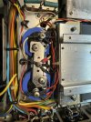
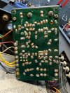
And the photo of the bottom of P800
IMG_0879.jpeg
 
Back
Top Bottom