• The move to the new server is done. There are some software and database maintenance updates in process. This has us passing the hat around to help out. We appreciate any donations. Seriously, even a dollar helps. The payment page may be found here - https://www.audiokarma.org/support.html

Why Recap Speakers and When?

I've read through the thread, trying to absorb all the info and advice. These are the caps in my cart. Are these appropriate for the T1000s? Are they "good enough" or should I spend more if significantly better products will make a real difference? Thanks for your help!


Dayton Audio PMPC-4.0 4.0uF 250V Precision Audio Capacitor
Part # 027-226

$3.97
x
Update
Remove
=
$7.94
Dayton Audio PMPC-8.2 8.2uF 250V Precision Audio Capacitor
Part # 027-242

$5.99
x
Update
Remove
=
$11.98
Dayton Audio PMPC-15 15uF 250V Precision Audio Capacitor
Part # 027-248

$10.68
x
Update
Remove
=
$42.72
47uF 100V Non-Polarized Capacitor
47uF 100V Electrolytic Non-Polarized Crossover Capacitor
Part # 027-352

$1.45
x
Update
Remove
=
$2.90
80uF 100V Non-Polarized Capacitor
80uF 100V Electrolytic Non-Polarized Crossover Capacitor
Part # 027-358

$1.98
x
Update
Remove
=
$3.96
 
Those parts are 'good enough' in my book.

The 47 uf electrolytic is starting to get a bit far from the target value of 42. I'd get a 33 uf plus an 8 uf and use them in parallel. That gives you 41, which is closer.

Or, it is possible to get real close by putting capacitors in series. Caps in series give you a combined value lower than the lowest of the two. For a few bucks more, you could get a 47 uf and a 400 uf. In series, that pair gives you 42.06 uf.

The formula for caps in series, btw, is (C1*C2)/(C1+C2). I made a spreadsheet that does this calculation for each combination of two that can be made with the electrolytic values Parts Express offers. That's 496 combinations....
 
Last edited:
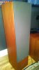
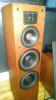
Caps are on the way--I spent a little bit more for what I determined to be slightly better specs. I'm very excited about taking on this little project and a little bit apprehensive, but I'm going to proceed slowly and step by step. These speakers are in such beautiful shape, I really want to give them the chance to show what they can do. The sound is impressive now, but I guess I'm hoping to regain some accuracy, sensitivity and tighter bass. We'll see! Here's a couple of pics to give you an idea of what nice shape they're in:


Dayton Audio PMPC-4.0 4.0uF 250V Precision Audio Capacitor 027-226 2 $3.97 $7.94
Dayton Audio PMPC-8.2 8.2uF 250V Precision Audio Capacitor 027-242 2 $5.99 $11.98
Solen 16uF 400V Polypropylene Capacitor 027-578 4 $9.29 $37.16
Dayton Audio PMPC-40 40uF 250V Precision Audio Capacitor 027-260 2 $22.07 $44.14
Audyn Cap Q4 82uF 400V MKP Metalized Polypropylene Foil Crossover Capacitor 027-124 2 $19.62 $39.24
 

Attachments

  • BA1.jpg
    BA1.jpg
    40.8 KB · Views: 19
  • BA2.jpg
    BA2.jpg
    48.8 KB · Views: 21
Thanks DQ! I'm really looking forward to hearing the results! Of course of I really fall in love with them the next step is a better receiver/amp...Oh boy!
 
Those parts are 'good enough' in my book.

The 47 uf electrolytic is starting to get a bit far from the target value of 42. I'd get a 33 uf plus an 8 uf and use them in parallel. That gives you 41, which is closer.

Or, it is possible to get real close by putting capacitors in series. Caps in series give you a combined value lower than the lowest of the two. For a few bucks more, you could get a 47 uf and a 400 uf. In series, that pair gives you 42.06 uf.

The formula for caps in series, btw, is (C1*C2)/(C1+C2). I made a spreadsheet that does this calculation for each combination of two that can be made with the electrolytic values Parts Express offers. That's 496 combinations....

Here's an online calculator for caps in series (scroll down a tad and enter the values).

http://www.radio-electronics.com/info/formulae/capacitance/capacitors-in-series.php
 
SNIP ... the next step is a better receiver/amp...Oh boy!
Just buy an amp!

Shop for an old FM tuner later. The ground must be heaving with them for chump change — depending on where you live.

I'd target a simple but effective amp. Put everything that line-current into it via an attenuator — if you have a power amp that does not have one.

If I were doing it all over again, I'd go to the new T-amp or other chip amp technology. But then one has to have very efficient speakers. Mine need a big load of juice, so I must stay with the big 40 pound box or start an audio revolution in my own home that will cost me the next round of convulsions in my annual budget.

Keep it simple. But that's only my my two bits worth — if that!
 
Last edited:
Caps are on the way--I spent a little bit more for what I determined to be slightly better specs. I'm very excited about taking on this little project and a little bit apprehensive, but I'm going to proceed slowly and step by step. These speakers are in such beautiful shape, I really want to give them the chance to show what they can do. The sound is impressive now, but I guess I'm hoping to regain some accuracy, sensitivity and tighter bass. We'll see! Here's a couple of pics to give you an idea of what nice shape they're in:


Dayton Audio PMPC-4.0 4.0uF 250V Precision Audio Capacitor 027-226 2 $3.97 $7.94
Dayton Audio PMPC-8.2 8.2uF 250V Precision Audio Capacitor 027-242 2 $5.99 $11.98
Solen 16uF 400V Polypropylene Capacitor 027-578 4 $9.29 $37.16
Dayton Audio PMPC-40 40uF 250V Precision Audio Capacitor 027-260 2 $22.07 $44.14
Audyn Cap Q4 82uF 400V MKP Metalized Polypropylene Foil Crossover Capacitor 027-124 2 $19.62 $39.24


Hmpf......no new inductors?
 
Inductors do not deteriorate with age.

Not saying they do, just know others have found bass improvement (tighter, more pronounced) going to inductors with larger gauge wire. I realize this is a mixed bag, not typically done unless there is pressing reason to do it, but I've had similar results with other low frequency circuits (high f chokes) I've rebuilt (never done this model though). Being the more expensive component of the crossover, many manufacturers skimp on inductor quality and there may be room for improvement here. Also, many replace wire leads with larger gauge and higher quality. Just bringing it up as it is a lot easier to do all these things at once while the patient is on the table.
 
Last edited:
Just buy an amp!

Shop for an old FM tuner later. The ground must be heaving with them for chump change — depending on where you live.

I'd target a simple but effective amp. Put everything that line-current into it via an attenuator — if you have a power amp that does not have one.

If I were doing it all over again, I'd go to the new T-amp or other chip amp technology. But then one has to have very efficient speakers. Mine need a big load of juice, so I must stay with the big 40 pound box or start an audio revolution in my own home that will cost me the next round of convulsions in my annual budget.

Keep it simple. But that's only my my two bits worth — if that!

What I'm planning on is a good used AVR with a full compliment of pre-outs. Possibly a slim-line Marantz to handle the codecs etc for my HT and then a a two-channel amp to drive the LR T1000s.
 
Soledering

Heh heh...guess what I'm doing this weekend...

Might I recommend a "chisel" tip for that soldering iron if it didn't come with one? Competent soldering was always a mystery to me until the box from PE with the chisel tips arrived.
 
Might I recommend a "chisel" tip for that soldering iron if it didn't come with one? Competent soldering was always a mystery to me until the box from PE with the chisel tips arrived.


I second this. I keep about 6 different tip sizes, pencil tip is great for board level soldering, but when you're trying to solder larger wires point-to-point, you want the heat dissipation of a medium chisel tip. Good luck on the recap!
 
I second this. I keep about 6 different tip sizes, pencil tip is great for board level soldering, but when you're trying to solder larger wires point-to-point, you want the heat dissipation of a medium chisel tip. Good luck on the recap!

RE: Board Level - even on some IC chips, that chisel is damn nice. On your average crossover board, the copper "pads" are large to the point of needing a transfer shovel tip.
 
What is better wire? Better for what? Inside speakers I would use any gauge that was convenient — but let's not get silly — say 18 to 22. And I'd use it on any driver stuffed into the box. Good — by good I mean reliable copper from a source that can be trusted and is not coated with some other metal. Preferably a Teflon insulator just for the sake of ruling out one miniscule set of worries, but not a big thing there. I do not hesitate to go to the local supplier and get two colors of 20 gauge single strand wire and be done with it. In one set of very modified speakers I used the same wire as I used as the main wire to the amp — orange and black, multi-stranded, twisted pair by a well-known maker — and just about the least expensive wire in the audio shop. No, not 'Monster'. I don't believe that boutique wire and special gauges make any difference. And if they did, I for one have other more important things to worry about. If you have any electrolytic caps in your equipment that are more than 7-10 years old and have been subjected to heat, I'd call that a focal point for attention. Internal speaker wire? Not an issue.

That being said, reflowed solder on connections and on the network might make a big difference if the speaker is a veteran or cold joints were performed on assembly

Thank you!
 
Last edited:
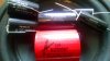
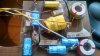
Well, I am about to find out how generous PE's return policy is! I got the crossover out of the T1000 today...hmm. First of all, the original caps are all 50V and the ones I ordered from PE are all 250V except for the 82uf, which was 400v. There is no way these caps are fitting on the crossover board--they're huge in comparison! I'll post a pic comparing the sizes. Also, although someone posted the cap values for the T1000, the value for one was incorrect. So, here's the question: do I try to obtain 50v caps with the proper values? This is my first recap project and I am definitely uncomfortable with the idea of constructing an entirely new crossover board to accommodate the really big caps! What would you do?
 
Well, I am about to find out how generous PE's return policy is! I got the crossover out of the T1000 today...hmm. First of all, the original caps are all 50V and the ones I ordered from PE are all 250V except for the 82uf, which was 400v. There is no way these caps are fitting on the crossover board--they're huge in comparison! I'll post a pic comparing the sizes. Also, although someone posted the cap values for the T1000, the value for one was incorrect. So, here's the question: do I try to obtain 50v caps with the proper values? This is my first recap project and I am definitely uncomfortable with the idea of constructing an entirely new crossover board to accommodate the really big caps! What would you do?

Here are a couple of pics showing the big difference in size of the caps!
 

Attachments

  • caps.jpg
    caps.jpg
    99.4 KB · Views: 47
  • crossover.jpg
    crossover.jpg
    113.2 KB · Views: 48
Back
Top Bottom