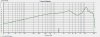
observations from this hack....
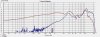
looking at the small FR & impedance graph on madisound's website, it looks like at ~3500hz, the actual woofer's impedance is more like 12 ohm...
https://www.madisound.com/catalog/images/userimages/fw146_t1.jpg
also, looking at this graph, looks like it's relatively flat to about 5khz, then has a 10-13db peak centered between 8&9khz.....
because the impedance is not 8ohm at the desired xover frequency, your low pass filter is not behaving as expected, I'm not good enough to have a feel as to the shape the crossover slope will have, but the .5mH coil would normally filter higher with a 12ohm vs. 8 ohm load (I think that's what gordon was alluding to)...with a simple 1st order butterworth, a .5mH coil crosses at 2500hz w/an 8 ohm load, but 3800 hz with a 12ohm load, using an online calculator...
using a standard 2nd order (12db/octave) filter at 3500, you should be down ~12db at ~7khz & ~24db@14khz, etc electrically, but you don't have a nice mechanical woofer roll off...typically the electrical component of the filter is combined with the mechanical roll-off of the woofer to get a higher than 2nd order slope (more like 4th order)....since your driver doesn't do this, but actually peaks in the higher frequency range, I'd think you'd want some sort of notch filter to kill that bump, and probably use a higher order (4th order?) low pass filter