


MadPik
New Member
Howdy All,
As some of you may recall I refurbished an X-101-C a few years ago and you all were a tremendous help. The amp has been up and running for a couple years now and sees a lot of use. However, when first troubleshooting the amp a curious "helper" adjusted the Phase Inverter pots before I noted where their original positions were. I've been using the amp with them in the "best guess" of what their original position was. However, it's always bugged me that they never got properly adjusted.
I'm don't have a distortion analyzer so the service manual procedure isn't feasible. I've read through countless threads on how to do the "quick and easy" adjustments but still can't seem to get my head around the process and/or the process is referring to different model amp.
The two methods that seem to make the most sense are from the Quick and Easy 400 Phase Inverter Adjust sticky and this method outlined here:
My hope is that you kind folks can dumb this down for me a little further with regards to specifics for the X-101-C (connect multi-meter lead to pin#, connect other lead to X, ect.)
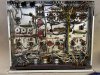
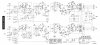
I've attached the corresponding pages from the manual and a pic of the X-101-C guts if that is helpful.

Thanks!
As some of you may recall I refurbished an X-101-C a few years ago and you all were a tremendous help. The amp has been up and running for a couple years now and sees a lot of use. However, when first troubleshooting the amp a curious "helper" adjusted the Phase Inverter pots before I noted where their original positions were. I've been using the amp with them in the "best guess" of what their original position was. However, it's always bugged me that they never got properly adjusted.
I'm don't have a distortion analyzer so the service manual procedure isn't feasible. I've read through countless threads on how to do the "quick and easy" adjustments but still can't seem to get my head around the process and/or the process is referring to different model amp.
The two methods that seem to make the most sense are from the Quick and Easy 400 Phase Inverter Adjust sticky and this method outlined here:
If you have a audio (sinewave) generator and a speaker dummy (resistive) load there is a simple trick used by old radiomans to balance PP audio amps:
1) connect a resistor load of adequate power and value to the amp speaker output. (a 8 ohms 25 to 30 watts wirewound resistor will be perfect)
2) disconnect the two common cathodes (pin 5) of the output tubes of the channel you are adjusting from ground and insert a inexpensive ( 4 or 8 ohms) radio speaker in serie between cathodes and ground. The DC current through the speaker will be too low to damage it, but don't use a high-quality expensive speaker.
3) Connect the audio generator (set at about 400 Hz) and drive your amp at about 3/4 of full power.
4) Adjust the phase splitter balance by ear, searching for the lowest signal coming from the speaker, listen very close and carefully for a null. (there will be no full cancellation of the signal but a cleary audible tonal change and drop in level) This will be very close to perfect AC balance of the splitter/output stage and minimum distorsion.
5) Remove the generator, test speaker and dummy load. Re-Connect the cathodes back to ground and you're done.
6) Repeat the process on the other channel for a stereo amp
For a more accurate adjustment you might replace the speaker by a 10 ohms resistor (value not critical) and an AC voltmeter (or oscilloscope) connected across it, then adjust the phase splitter for the lowest indication. The old "speaker trick" works quite well too, as the ear is very sensitive to small tonal and level changes.
The whole process will take you less than 10 minutes and you only need a audio generator and a high wattage load resistor.
After the adjustment is completed don't move the phase splitter and output tubes from their position and seal the pot with nail varnish.
Of course the IMD method recommended by FISHER is more accurate ( a modern spectrum analyzer would be even better) but most DIYers don't have the required test equipment. Still, the crude method described above is better than the "leave it as it is" method.
My hope is that you kind folks can dumb this down for me a little further with regards to specifics for the X-101-C (connect multi-meter lead to pin#, connect other lead to X, ect.)
I've attached the corresponding pages from the manual and a pic of the X-101-C guts if that is helpful.
Thanks!