• The move to the new server is done. There are some software and database maintenance updates in process. This has us passing the hat around to help out. We appreciate any donations. Seriously, even a dollar helps. The payment page may be found here - https://www.audiokarma.org/support.html

XR6 Isoplanar Loudspeakers on the way

Bill Legal at millersound in PA will do them for 25-30 each and his turn around time is one week.

Thanks, but the mids are going back to the factory. Maybe we can talk re-foaming the 12" bass drivers. BTW.. for you rebuilders, black stainless screws are available from McMaster at: http://www.mcmaster.com/#tapping-screws/

Click on Sheet Metal Screws, Standard Point, 18-8 Stainless Steel, Black Finish, Pan Head, Phillips. Those should work great!


-Greg
 
Last edited:
Gregory, it is nice to see you posting all the little details like the screws and sources like McMaster. Being able to get to this sort of information is what makes this place great - well, that and being able to 'ride along' with your rebuild.

Cheers,

David
 
jdwk said:
Bill Legal at millersound in PA will do them for 25-30 each and his turn around time is one week.
MX117.MC7150 said:
Thanks. I do hate to waste money.

Have already budgeted for the UMs. It might be a good idea to contact Millersound, as the domes haven't been shipped out yet.

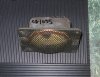
Here are a couple more photos of the 036-035 driver:

XR6_UM_edge.jpg
Don't worry about the Sharpie marker, it can come off with acetone.


XR6_UM_rear.jpg


Still undecided as to where to send the 12" woofers for refoam. These are critical components IMHO since bass compensation can drive them `wild´ in the low bass range. They just need to be refoamed, and it must be done correctly so as NOT to change the mechanical properties much from the original. Roger Russell says "do not include getting new cones. Only the surrounds need to be replaced."

BTW...today is removal of the woofers, and crossover inspection!


-Greg
 
Last edited:
Have already budgeted for the UMs. It might be a good idea to contact Millersound, as the domes haven't been shipped out yet. Still undecided as to where to send the 12" woofers for refoam. These are critical components IMHO since bass compensation can drive them `wild´ in the low bass range. They just need to be refoamed, and it must be done correctly so as NOT to change the mechanical properties much from the original. Roger Russell says "do not include getting new cones. Only the surrounds need to be replaced." -Gregory
I'm guessing that the factory does considerably less speaker work than many shops that specialize in doing only speakers. You might want to ask in the speaker forum who is recommended. I had a set of 10" woofers refoamed by an outfit in St. Paul (Midwest Speaker Repair) and they did an excellent job for $75/the pair. And, when a magnet busted loose on a Yamaha NS-1000 pair that I've got, Audio Atlanta's main speaker person (I've forgotten who it is, as it has been a number of years - but he posts in the speaker & vintage ss forums from time-to-time) did an excellent job of rebuilding the woofer and aligning and remounting the magnet structure correctly. The NS-1000 pair still sings at my brother's.
 
Now for the GOOD part!!

Woofer removal - S/N 1634

First we'll start of with speaker S/N 1634, the one with the undersized Upper-Mid (which was functioning BTW) mounting screws. This cabinet was easy work on laying flat on its back. All screws were tight but came out by hand with LOTS of downward force. At no time did the Phillips screwdriver jump the slots or pop out and stab the baffle or cone.

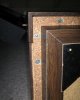
The first step is to remove the lower wooden trim assembly:

CD1634_005.jpg


CD1634_004.jpg


The face board/trim assembly can be set on the bottom riser, as the LED indicator wires seem to hold it from falling off pretty well. There was some crud on the lower ledge where the LED guard mounts.. also on the inside of the trim assembly.

CD1634_008.jpg


The woofer came out without any prying or tearing of the baffle plate. THAT was a BIG relief, as I feared for the worst. There are rubber gaskets installed between the driver basket and baffle. Both of those were in tact and very much reusable!!

CD1634_013.jpg


The crud easily came off from the surface of the lower ledge. Looks great!

CD1634_017.jpg


Crossover removal - S/N 1634

There was no trouble removing the crossover face-plate or network PCB. Best to cover the area under, and on the front edge of the cabinet top plate with a folded towel to avoid nicks, scratches or other damage to the finish.

CD1634_025.jpg


Here's a view of the removed crossover PCB and face-plate.

CD1634_027.jpg


Working on S/N 1634 was straightforward and without any issues. All connections and orientations, etc. were recorded in the notebook for reference. As you'll see in the next post, S/N 1635 was a MUCH bigger challenge and there were some surprises!!


-Greg
 
Last edited:
Now for the Good Part 2

Woofer removal - S/N 1635

S/N 1635, which would seem to be the next production unit and sequential serial number, was different in many ways from S/N 1634.

First off the screws holding the lower trim board apparently wobbled while being driven into their holes leaving cuts in the vinyl riser. This happened on all three of the front screws.
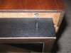
CD1635_001.jpg


The next discovery for this speaker cabinet was the woofer was in much worse shape than S/N 1634. Here is a view of the separated and TORN surround. This was the woofer making the `whop-whop-whop´ sound like a Huey chopper. Not so bad really...as they'll be re-foamed soon.
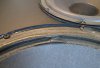
CD1635_005.jpg


The surrounds of THIS driver were in bad shape. When removing the screws, the deteriorated material tore away and came up on the screw heads. The white marks that you see are from merely touching the baffle. They easily wipe off with a tack cloth.
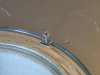
CD1635_011.jpg


Once the woofer was out, it became evident that shreds of surround material had detached and fallen into the damping material. It wasn't too difficult to vacuum the pieces out with a Dirt Devil Cone however. The quality of damping material was good and didn't get sucked out with the vacuum. Most of the fallen surround material was from the TOP edge, and a buildup of damping fibers had collected at the BOTTOM of the surround.

I'm starting to believe the woofer in S/N 1635 could be some two years older than the one in S/N 1634!!
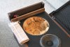
CD1635_027.jpg


Here you can see in the pic below, all of the deteriorated surround fragments are gone!! Also the crud has been removed from the lower ledge.

CD1635_029.jpg


The cabinet grill/doors have high quality hinges!!
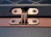
CD1635_023.jpg


S/N 1635 had a broken terminal/connector tab (RED) on the left side of the photo. Also the connector cover could use a shot of spray paint. No problem. :D

CD1635_004.jpg


Crossover removal - S/N 1635

Here is where the real headaches and surprises started. Screws holding the crossover cover plate were under-size with washers, just like the Upper-Mid screws in S/N 1634. The crossover board had a plastic loop or PULL RING that lasted about 1 minute and then broke!! The network PCB was in the housing EXTREMELY tight and would not come out for at least an hour!! (More on this late.)

Here is a photo of the crossover housing AFTER the PCB was finally out.

CD1635_034.jpg


Notice the housing holes (left side in photo) didn't line up well with the cabinet holes. More on this story in the CROSSOVER post... coming next!!


-Greg

 
Last edited:
Now for the Good Part 3

Crossover Removal and Comparison

As already stated, the network or crossover PCB came out of its housing in S/N 1634 without difficulty. S/N 1635 was a whole different matter. There was a plastic loop or `pull ring´ on the top-center of 1635. The crossover board was in EXTREMELY tight and the LOOP broke in the first minute or two. A hook tool was used to pull 1634 board out, but it wouldn't budge in 1635.

It was VERY upsetting. The words PO'd come to mind.

The next decision with to disconnect the FUSE terminals from the crossover, but they were so tight, that the soldered male terminals pulled out of the PCB!! :rant:


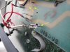
In the photo below you can see the broken `board pull loop,´ the quick-disconnect fuse terminals and the holes that they ripped out of!!

CD1635_055.jpg
Soldered QD terminals ripped out of PCB from the force needed to disconnect them.


Mounting goop interferes with PCB removal

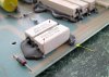
Not only was the crossover housing being squished by the misaligned holes, but the HOT GLUE that mounted the inductor on the left, and power resistors on the right were preventing the board from coming out!!

CD1635_047.jpg
Inductor mounted too close to board edge, mounting goop hung-up on PCB rail barbs resulting in a LOT of damage.


CD1635_058.jpg
Date codes on resistors. Mounting goop also hung-up on PCB rail barbs and badly damaged them.


The crossover housing had to be removed from the cabinet and PADS laid over its edges so that GREAT force could be applied to PULL the PCB. It was very difficult NOT to break or bend ANY of the parts.


Dissimilar Crossover Networks

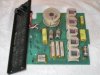
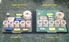
Here is a photo of S/N 1634 and 1635 crossover PCBs placed next to each other on the bench. After studying the date codes and looking at other features, I'd have to say the CD1634 network was built in ~1977, and CD1635 network was built in ~1979.

CD1635_066.jpg


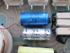
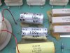
Here are dissimilar electrolytic caps:

CD1635_048.jpg


CD1635_049.jpg


Quick Disconnect terminals ripped out


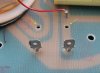
Some views of the S/N 1635 QD terminals that ripped out of the crossover board while trying to unplug the FUSE wires in a normal way:

CD1635_046.jpg


CD1635_059.jpg


With all these observations taken together.. I'd have to say again that S/N 1634 was built in 1979 and S/N 1635 was built as much as two years previously, or maybe an older crossover was installed. Another observation...the two face-plate FUSE wires were of different gauge and length.

Not sure how these two speakers could be sequential S/N's.


Conclusion

As was known before purchase, both woofers and one Upper-Mid needed rebuilding. It now looks like some minor repairs will be needed to the crossovers. Perhaps the wires should be SOLDERED instead of connectorized.

I think the crossover electrolytics should be replaced with NEW and similar components. That should not be a problem.


-Greg
 
Last edited:

A few more pics of the FUN speaker project on Saturday!!


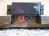
XR6 face plates on table. The fuse holders are slightly different.

XR6_face_plates.jpg


Back side of face plates. They have different wire size and length.

XR6_face_plates_back.jpg


Upper-mid domes sitting on the desk..

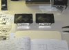
XR6_domes_II.jpg


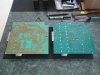
Two dissimilar crossover boards on the bench (copper side.) One on left from 1977? and on right from 1979?

XR6_crossovers_back.jpg


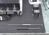
Tools used to pull crossover boards
– except for the one that was`stuck.´

XR6_hooks.jpg

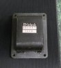
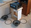
The back side of a MC 2505, and two XR6 LED lamp covers on the right.


The woofers and gaskets seem to congregate around the amplifier. Hmm.. wonder why? :)

XR6_woofers.jpg


An all-around fun and challenging project.


-Greg
 
Last edited:
Question: Is it advisable to replace the ELECTROLYTIC caps on the crossover networks? -Gregory
To me, a recap is a recap. Especially as there are relatively few. Match them as Ron-C suggested in the other thread. They are the same age as the others.
 
To me, a recap is a recap. Especially as there are relatively few. Match them as Ron-C suggested in the other thread. They are the same age as the others.

Thanks for the reply.

I get what Ron-C said in the other thread, but your point isn't too clear. Which are the same age as what others? Are you suggesting to replace all the caps? The PE caps are cheap. I could buy eight of them for what Mc Parts quoted for each replacement electrolytic cap. What are the tolerances? The Mc part numbers are:

Code:
C1,C3      Electrolytic     50uF    100V     Mc #066-192    Qty: 4
C2         Electrolytic     25uF    100V     Mc #066-189    Qty: 2

Here are the PE caps: http://www.parts-express.com/crossover-capacitor-index.cfm?CFID=717288 (hover over headings)

and the electrolytics: http://www.parts-express.com/non-polorized-electrolytic-capacitors.cfm


-Greg
 
Last edited:
My point is if you are doing a recap why would you not replace them all? All the caps are the same age. And, as they are relatively inexpensive, if you have a capacitance meter, as Ron suggested, get extras and match them to insure the same response profile from both speakers. I don't understand buying spares from McIntosh parts unless you can't find them elsewhere.
 
Putting things in perspective

Doing an analysis of date codes on the crossover components, the latest part on #1634 was 7926 (week 26 of 1979) and for #1635 was 7752 (week 52 of 1977). The seller bought the speakers NEW in Aug 1980 per the manual packets.

In fall 1980 I was a senior in college, just months after the XR6s were purchased from a McIntosh dealer. Now I'm early 50's and grey... but the XR6s sure do look great!!

Code:
CROSSOVER COMPONENT DATE CODES

     CD1634  CD1635
     ------  ------
C1            7743
C2
C3            7744
C4    7911    7752
C5    7926    7723
C6    7819    7739
R1            7723
R2    7819    7723
R3
R4    7839    7717
R5    7819    7723


-Greg
 
Last edited:
Is that a Yamaha CT-1010? Still an excellent tuner after a recap and alignment.

It's a CT-800, however it's long gone. I sold it after acquiring the MR 77 and MR 80.


Getting back to the XR6 topic

Did you see the reply from Ron-C on the crossover caps: XR6 Crossover Caps - SPEAKER forum ?

Nice
!!

The drivers haven't been shipped yet, as I'm still doing some homework on refoaming.

Might even do the woofers here at home.


-Greg
 
Last edited:
Have decided to replace ALL of the crossover board caps and resistors on the advise of Ron-C. The multi-purpose hot glue sticks will adhere to Poly caps (like on the Thiel crossovers) and should stand up to the power resistor heat? or not? The caps are coming from PE, and the precision Mills resistors from: www.soniccraft.com

When complete the components left and right (except inductors which are fine) will be identical. The clashing black and yellow goop can be chipped away, and replacement parts attached with clear stuff!! It probably won't be done until Memorial Day weekend... and I'll post some pics.

What a GREAT project!!


-Gregory
 
Last edited:

An update on the XR6 Project


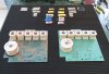
The crossover boards were dismantled Friday night and components measured for accuracy this morning. The following is a pic of the stripped network boards and the components labeled with their raw uncorrected values. That's S/N 1635 on the left and S/N 1634 on the right:

XR6_parts_removed.jpg
Crossover boards side-by-side, 1635 on the left circa 1977, and 1634 on right circa 1979. The BLACK mounting goop on the LEFT made it VERY difficult to remove the PCB!!


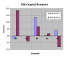
In order to keep this thread on a top-level McIntosh product restoration topic, detailed questions and analysis of the crossovers are posted in the AK SPEAKER forum. Let's have a summary look at the measured values relative to the schematic.
XR6_R_error.png


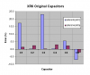
XR6_C_error.png

XR6_R_error.png


C1 and C3 in violet bars above are the values of the older BLUE electrolytics. The NEW parts will be MUCH more accurate!! Some of the copper pads lifted from the boards despite being very careful and using best practice. These pads are close enough to jump the leads over and solder together.

It will be at least 10 weeks before the drivers are completed so there's plenty of time to build-up a set of MATCHED crossover components for these babies!!


-Greg
 
Last edited:
Having matched crossover components, left-right will help with stable stereo imaging. If your old caps measure different left right then the sound will be lacking. Mills are also available from PE.

Thanks,
Ron-C
 
Having matched crossover components, left-right will help with stable stereo imaging. If your old caps measure different left right then the sound will be lacking. Mills are also available from PE.

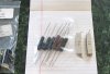
Yes.. I've purchased Mills resistors from an outfit in Arkansas, and they were on sale!! The 3 and 5 ohms resistors all measured 3.0 and 5.0 ohms (cannot resolve 0.01 ohms.) The 100 and 470 ohm resistors were +1.0/-0.64% and I'd like to keep everything within +/-0.5% so may order a couple more and select two from the bunch. Maybe not. :)

XR6_resistors.jpg


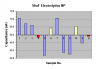
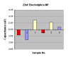
The cap values came out really well. After measuring two batches with the DMM, error factors of 0.1398 and 0.1397 fell out of the numbers, so that's what was used for error correction. The NP cap pairs are within +0.54/-0.17% which is essentially inside +/-0.5%.


Charts of the selected pairs are posted below.

50uF_NP_pairs.png

22uF_NP_pairs.png


Problem

The only issue is...the schematic calls for 25uF caps, so I'll need to add 3uF in parallel. This question {what/how to add in parallel} is posted in the SPEAKERS forum of AK under thread "Crossover caps?".


-Greg
 
Last edited:
Back
Top Bottom