


thebeekeeper
New Member
So I'm trouble shooting a Yamaha amp that appears flat dead. It was working, was moved a few hundred miles and is now dead.
Quick check with my multi-meter shows 120vac coming in, fuse fine, but from the first power filter board to the transformer I have 0 volts. I pulled the connector to the transformer, and read 120 v on the pins. I put on the connector and read 0 volts. I thought it was the connector. So I went with some jumper wires and proved as soon as the transformer is connected, it goes from 120 to 0 v. Odd.
I disconnected the 2ndary from the transformer. Repeated. 0 v. This does not compute with my electrical engineering brain. The fuse is not blowing, the transformer is not shorted. Resistance is 2-3 ohms on the primary, and resistance is not impedance when it comes to Xformers.
My first guess is some self protection circuit cuts off voltage. But I don't ever hear the relay clicking. So i'm stumped.
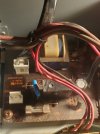
Quick check with my multi-meter shows 120vac coming in, fuse fine, but from the first power filter board to the transformer I have 0 volts. I pulled the connector to the transformer, and read 120 v on the pins. I put on the connector and read 0 volts. I thought it was the connector. So I went with some jumper wires and proved as soon as the transformer is connected, it goes from 120 to 0 v. Odd.
I disconnected the 2ndary from the transformer. Repeated. 0 v. This does not compute with my electrical engineering brain. The fuse is not blowing, the transformer is not shorted. Resistance is 2-3 ohms on the primary, and resistance is not impedance when it comes to Xformers.
My first guess is some self protection circuit cuts off voltage. But I don't ever hear the relay clicking. So i'm stumped.
Last edited:

