

You are using an out of date browser. It may not display this or other websites correctly.
You should upgrade or use an alternative browser.
You should upgrade or use an alternative browser.


950 or 960 or 960 II ?i have yamaha A-950 amplifier
thanks avionic for your kind reply950 or 960 or 960 II ?
its yamaha A-950
i recapped that capitor but still it doesnt work out
i m much confused for this amp because nothing seems to be wrong but still not working withouth dim bulb tester
but one thing click on my kind that in this attached pic , i think the place between these big black capacitors needs to be cleaned?
Attachments
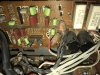
thanks redrooster for your replyThat looks like the dreaded brown conductive glue between those big black capacitors, it may be causing a short? The capacitors need to be de-soldered from the board and the glue scraped off. Is that a disconnected wire I see on the fuse board?
yes the amp is a kind of short.
i will de sold it then will clean it. no the wire is ok, because of pic quality it looks like disconnected
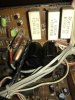
They are suppose to get hot.. Thats why they are so large.. ie. 5 watt resistors . Measure the DC voltage on those resistor legs .. Should be +/- 22 vdc...these white resistance in the attached pic are heating up too much
2 legs have + 22 vdc
1 leg has -22 vdc
3 legs have zero vdc -- chassis ground
Last edited:
ok
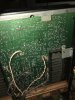
also i m attaching pic of board, please tell me where does it needbto resoldering ?
also i m attaching pic of board, please tell me where does it needbto resoldering ?
Attachments
-
 A3337D6B-22A5-4184-82F2-82D2858E4417.jpeg139.4 KB · Views: 37
 -
 74774969-84A6-43E2-B79B-8869C74947D9.jpeg91.9 KB · Views: 35
 -
 03B4043D-E1AF-47EB-A93C-5C9AD1A827CC.jpeg181.7 KB · Views: 36
 -
 B0E244ED-F744-4C4B-9995-E179AF51F0EE.jpeg156.4 KB · Views: 35
 -
 6C4CAF7C-1CCD-4877-89F9-5D268B72C184.jpeg161 KB · Views: 34
 -
 ED58816D-AE94-4506-A00E-107FE5ECC5FA.jpeg146.3 KB · Views: 35

Hamish119
Active Member
If you're really unlucky, it may be 2x duff transistors. Or it may be a duff resistor. Or a combination of both......There is no class A in the right channel.
...One side has increased voltage the other is as if I hadn't pressed the auto class a button.
The tech said i should just live with it, since it's one dead transistor out of 50+ ...
You know TR123 is functional because TR121 & TR125 perform as expected when the CLASS A button is engaged - your supplied pictures confirm this...
What you don't know is what's (NOT) happening with TR122 & TR126 or the resistors in between...
Procedure:
Speakers (or any other load) and sources must be disconnected, volume @ minimum.
Step 1 - With power removed;
Test the functionality of the transistors and resistors in the failed path.
If you're unable to locate the problem, proceed with extreme caution to Step 2 (mistakes will destroy the amplifier).
Step 2 - With power applied using a (<100W) bulb limiter.
Compare the Base, Emitter and Collector voltages of TR122 (unknown) with TR121 (reference) and TR126 (unknown) with TR125 (reference), without and with the CLASS A button engaged.
Note the results.
Resolve the issue.
Know your limitations!
Good Luck!
Last edited:
Th
Thanks for this. Sadly it went up in smoke one day, and burned a resistor. It's far far on the back bench now. I may just get a A-1020If you're really unlucky, it may be 2x duff transistors. Or it may be a duff resistor. Or a combination of both...
You know TR123 is functional because TR121 & TR125 perform as expected when the CLASS A button is engaged - your supplied pictures confirm this...
What you don't know is what's (NOT) happening with TR122 & TR126 or the resistors in between...
Procedure:
Speakers (or any other load) and sources must be disconnected, volume @ minimum.
Step 1 - With power removed;
Test the functionality of the transistors and resistors in the failed path.
If you're unable to locate the problem, proceed with extreme caution to Step 2 (mistakes will destroy the amplifier).
Step 2 - With power applied using a (<100W) bulb limiter.
Compare the Base, Emitter and Collector voltages of TR122 (unknown) with TR121 (reference) and TR126 (unknown) with TR125 (reference), without and with the CLASS A button engaged.
Note the results.
Resolve the issue.
View attachment 2255085
Know your limitations!
Good Luck!
i have removed the glue from these big black capacitors but still it doesnt work. these white resistance in the attached pic are heating up too much when i connect the amp directly to the AC supply.
please help me seniors
Hello first time on Audiokarma.
Those resistors are getting voltage drop from full dc supply voltage (around +/-70V) for supply +/-22Volts for differential amplifiers, phono preamp and preamplifier. Normally that stages takes around 110 mA. So the power loss on those elements are around 5 watts per + and 5 watts for - supply. It is normal that they are heaitng. But they are connected in parralel, so each of them are lossing some part of power. I think the normal temperature of those elements at work, can be 60-70 celcius. It is normal situation. I think it is not a your problem.
Probably if the bulbs are lightning when you are connecting power through a bulbs, the problem is that power, driver and pre-driver transistors can be burned. You should check them is there any failure.
Last edited:

konstantin62
New Member
Всем привет ! У моей Yamaha A1000 тоже проблемы! Почитал и сделал замеры по совету неравнодушных участников этого форума. Далее почему-то все повествование обрывается, без логического завершения и решения вопроса по описываемой проблеме. Поначалу радовали ответы грамотных помощников по устранению неполадок. Что случилось!? А где продолжение по этому вопросу!?
konstantin62
New Member
Hi all ! My Yamaha A1000 has problems too! I read and and took measurements on the advice of not indifferent participants in this forum. Further, for some reason, the entire narrative breaks off, without a logical conclusion and a solution to the issue on the described problem. At first, the answers of competent troubleshooting assistants were pleasing. What happened!? And where is the continuation on this issue!?Если уж совсем не повезет, то может быть 2x дафф транзисторы. Или это может быть резистор duff. Или сочетание того и другого...
Вы знаете, что TR123 работает, потому что TR121 и TR125 работают, как и ожидалось, когда нажата кнопка CLASS A - предоставленные вами изображения подтверждают это...
Чего вы не знаете, так это того, что (НЕ) происходит с TR122 и TR126 или резисторами между ними...
Процедура:
Динамики (или любая другая нагрузка) и источники должны быть отключены, громкость должна быть минимальной.
Шаг 1 - При отключенном питании;
Проверьте работоспособность транзисторов и резисторов на неисправном пути.
Если вы не можете определить местонахождение проблемы, переходите с особой осторожностью к шагу 2 (ошибки разрушат усилитель).
Шаг 2. При подаче питания с использованием ограничителя лампы (<100 Вт).
Сравните напряжения базы, эмиттера и коллектора TR122 (неизвестно) с TR121 (эталон) и TR126 (неизвестно) с TR125 (эталон), без и с нажатой кнопкой КЛАССА А.
Обратите внимание на результаты.
Решите проблему.
View attachment 2255085
Знай свои ограничения !
Удачи!
konstantin62
New Member
*Всем привет ! У моей Yamaha A1000 тоже проблемы! Почитал и сделал замеры по совету неравнодушных участников этого форума. Далее почему-то все повествование обрывается, без логического завершения и решения вопроса по описываемой проблеме. Поначалу радовали ответы грамотных помощников по устранению неполадок. Что случилось!? А где продолжение по этому вопросу!?Они должны нагреваться.. Вот почему они такие большие.. т.е. Резисторы на 5 ватт. Измерьте постоянное напряжение на этих ножках резистора. Должно быть +/- 22 В постоянного тока...
2 ножки + 22 В постоянного тока
1 нога имеет -22 В постоянного тока
3 ножки имеют нулевое напряжение постоянного тока - заземление шасси

OMGCat!
Super Member
Hi all ! My Yamaha A1000 has problems too! I read and and took measurements on the advice of not indifferent participants in this forum. Further, for some reason, the entire narrative breaks off, without a logical conclusion and a solution to the issue on the described problem. At first, the answers of competent troubleshooting assistants were pleasing. What happened!? And where is the continuation on this issue!?
Once the threads get this long people usually end up talking over each other with a bunch of different issues.
Start a new thread and add what you’ve already gone through and tested then go from there.

plugto
Well-Known Member
I have a question to all owners of the A-1000, did anyone ever notice when running log sweeps from low to high, that the amp oscillates? I remember reading in an amp article from John Curl something about why amps do this. I haven't tried it on my current large amp an Anthem P5 statement, and never tried it on my old refurbished Nikko Alpha 440s that I am using for height amps in an Atmos system. Just curious if it was only my amp that did this.