
• The move to the new server is done. There are some software and database maintenance updates in process. This has us passing the hat around to help out. We appreciate any donations. Seriously, even a dollar helps. The payment page may be found here - https://www.audiokarma.org/support.html

Yamaha a960-II recap

worldofjani

New Member
Hi!

I aquired a Yamaha a960-II with leaking caps, and I would need some advise on which capacitors I should use.

From what I have gathered from the forum, Panasonic FC seems like a good all-round capacitor, and Nichicon UKW could be used for signal paths.

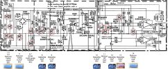
Added a schematic with capacitor locations marked and information of the types of capacitors sitting there now.. I am not quite sure which capacitors are on the power path and which are on the signal path.. What throws me off is the rectifier bridge ("power") and then the two large Elnas which are audio grade.

Could I just replace everything with FC or UKW ?.. or perhaps any other recommendations ?

TWSS is a general purpose, but not so sure of the Matushita ones, especially "13", lavender, is it audio grade ?

Also, the 0.47 and 0.22, can those be replaced with film capacitor (Wima MKS?) as those are hard to find(possibly not available) in FC and UKW.. Or should I go for electrolytic in some other series ?

Regards
Jani
 

Attachments

  • schema1.jpg
    schema1.jpg
    114.4 KB · Views: 14
  • TWSS.pdf
    TWSS.pdf
    318.3 KB · Views: 6
Register to hide this ad
The power supply capacitors can be audio grade- audio needs hum and noise free power. You may not hear any difference between audio or regular grade, they both have really low ESR and do the job, but since they are so big and visible through the ventilation slots manufacturers tend to use nice stuff there to inspire confidence.

My response should be flavored with a pinch of salt, because I tend to be more practical than "audiophile" on this, but I do have a good education and lot of experience. Like a mechanic friend told me about motor oil- you can winge about what expensive boutique this or that flavor to try to optimize that last 2% so you can feel good about it, but at the end of the day all the engine knows is new cheap oil changed regularly feels far better than old used expensive oil.

If you have leaky caps, you probably have all sorts of much bigger problems. 99% improvement will be had in replacing them with any kind of decent, modern, good capacitor. Using =any= top name capacitor (Nichicon, Matsushita, Panasonic, Elna, Rubycon, etc) will serve you very well. Avoid the random gibberish or phony named (my favorite is "Nilchicon") dirt cheap, often counterfeit "they measure good now, and might work for a while" caps.

What exact flavor of capacitor, from there, will likely make minuscule, inaudible, intangible differences, I find not worth worrying about. Keep in mind, that you want to choose voltage ratings that are no more than perhaps twice the original. Newer caps will be much smaller typically than the originals for the same value and voltage rating, so you may be tempted to go sky high on voltage. A "happy" electrolytic runs at about 2/3 of it's rated voltage- That keeps it formed, but gives it headroom for surges/spikes, etc.

I also find that just as with "shrinkflation", new (especially cheap) capacitors tend to be a lot more skrimpy on capacitance than older caps. While capacitance can become inflated with age as the electrolyte dries and the foil comes into closer contact, I find that vintage capacitors routinely run a bit higher than the rated capacitance, while newer cheap caps run at the lower end of the stated tolerance. For most places, this is not much of a problem- well designed electronics are generally tolerant to normal component variations, and values are conservatively chosen to make sure there is enough capacitance with margin. I have a cheap capacitance meter, which you can get on ebay/amazon etc that measures leakage and ESR with passable accuracy. I like to measure and record each old capacitor, just for my education, and measure each new capacitor before I install it. I do find dogs from time to time. In the end you will likely find that 80% or more of the capacitors you replace are really not bad at all, just old. The key caps that were causing all of the problems will boil down to just a very few. Sometimes, I will just pull caps, test them, and put them back in if the replacement is not actually any better. But then again, I can go back in and easily replace one that later goes bad at any time- I don't need to future-proof them, as by then I will have either upgraded the equipment, or died.

Be especially careful where absolute capacitance value really matters- in feedback paths, in filtering, etc, as these affect stability. May be only a couple in the entire amplifier. Ask here with schematics and there will be guidance. From the fragment of schematic you have posted, this appears to be all auxilary, power, protect type functions, not a lot of prime audio path, so I think you have quite a bit more leeway in this area.
 
Last edited:
Thank you for your answer, it clears up many things :)

I have looked at mouser and digikey, but not sure what to use for the 0.47uf, 0.22uf and 2.2uF BP caps. Looks like Nichicon ES/MUSE 2,2uF BPs are not available, any suggestions for a replacement would be very welcome. There are 2,2uF audio grade BPs on the part of the PCB which I did not include the schematic for.

Regards
Jani
 
Yes- I agree- for the 1uF and lower that were populated with electrolytic or bipolar electrolytic, I generally replace with whatever poly, polyester, polypropylene, MKP, film (there are many confusing names for the variants of basic film capacitors with some having a passionate favorite). The Wima are excellent. Boxy, inflexible lead spacing, but excellent if you can fit them. I'm not as picky- some types will fit the lead spacing better than others. Here is a good selection to look through: (Film capacitor category at AES)

If I can fit the big yellow axial lead caps are good for tube amps with point to point wiring, for PCB's I will either use the radial lead orange drop type, radial lead brown type, or the radial lead green type, depending upon what fits best. Hard to go wrong, and a superior cap to the little electrolytic.

These types of film caps start getting pretty big for anything above about 0.47uF, so 1uF you may not have room for. For the 2.2uF bipolar, I would try to replace them with a new bipolar electrolytic if you can, unless you are lucky enough to fit a monster film cap in there.

Oh- the comment about voltage rating on electrolytics does not really apply to film caps. You have to use caps with a rating that is higher than the voltage they will be exposed to, but it's not uncommon for film caps to have high voltage ratings (>100V or more) and this excess voltage rating does not really affect lifespan or performance, as there is no electrolyte that has to stay formed- they are a foil/dielectric fixed capacitors.
 
Last edited:

Well you rock! I think you made my point for me.

Sub-1uF electrolytics can be really small, often 2.5mm spacing. =Most= typical poly radial lead caps will be much bigger than that- more like 5, or 7 to 10mm spacing, which is large compared to the original spacing, won't easily fit in the original PCB, unless you want it to look stupid, or mount it from the underside. The particular cap you point to will not fit 2.5mm, so "BS". The particular one special line that fits 2.5mm sound great. link?
Either way, it does not make my 'general' statement any less accurate.

Anyway, just trying to be helpful.
 
Sub-1uF electrolytics can be really small, often 2.5mm spacing.
4 out of 5 times, the pcb lead spacing for smaller value 'lytics is 5mm and the capacitor leads are bent to fit. and yes, a film with 5mm lead spacing will drop right in

but for those times where the actual pcb spacing is 2.5mm and the value is 1uf or less then:


...there are actually 3 series that have 2.5mm spacing..

i do not know why .68uf does not show up under that search but it is here


and if i have to, i will bend the leads so that a film cap with 5mm lead spacing will fit in a pcb with 2.5mm spaced holes.... and it doesn't look stupid.
 
4 out of 5 times, the pcb lead spacing for smaller value 'lytics is 5mm and the capacitor leads are bent to fit. and yes, a film with 5mm lead spacing will drop right in

but for those times where the actual pcb spacing is 2.5mm and the value is 1uf or less then:
Tip: Purchase your film caps with "ammo tape/tape " packaging for longer leads.
 
Thanks to everyone for the replies, very useful information !
Caps have now been ordered, mostly Panasonic FC, a couple of Nichicon where FC;s were not available and Wima film caps for the lower values.
I can update this thread with a list of capacitors used in this amp after recapping if someone else needs it.
 
I have now recapped everything, and it sounds G R E A T.. Took a while since I had to renovate the balance/bass/loudness sliders and figure out a broken op-amp on the tone control board.

However, I got one hurdle left, and it is replacing the Incandescent/light bulbs.

The servicemanual says the lamps are 8.7V 150mA, and but I just don't understand how it all works. If I disconnect the connector going to the lamp circuit, there is approx 55V ( without load? ) on the connector. While connected, the voltage depends on how many lamps are lit. It regulates depending on the load (I think?).

55V is the operating voltage for the amplifier, and looking at the schematic, its connected to that source, so it might be normal to have 55V on the connector with the lamps disconnected?

There are two transistors and a zener diode involved and in the circuitry and "8.7" written below the Collector of TR348. Since the lamps are in series, wouldn't 8.7V be a bit low as whole for the output to the lamp circuitry ? TR347, TR348 and D336 checks out with component tester.

While searching on the net, I found several LED/lamp mods where power resistors are involved:
Example of a A-760 with LED modification with 2W+3W resistors ; http://gigapod.free.fr/Yamaha_A760.html

Looking at the schematic for the next bigger model A-960II, it appears the bulbs are driven by a transistor current source of ~100 mA DC, and they are in fact connected in series - those not in use are being shorted out.

In the 960II, this is found around transistor TR348. Current is determined by
I = (V(zener D336) - Vbe(TR348)) / (R474 || R475)
~= 11.4 V / 110 ohms stock
Above quote from https://www.diyaudio.com/community/threads/help-replacing-yamaha-a760ii-lamps-with-leds.241943/

If there is 100mA, and 55V, using P=U*I = 5.5 Watts ? (hence the use of power resistors?)

I tried with 2W power resistors, and it does the job, but they get very hot and does not feel ideal at all.. Somewhere I read that replacing R474/R475 with higher values would bring the current down.

So my question is, If I'd do a LED mod, would swapping R474/R475 mitigate using power resistors ? Or is there another/better way to do it ? Thankful for any insight in this issue.

Regards
Jani
 

Attachments

Back
Top Bottom