• The move to the new server is done. There are some software and database maintenance updates in process. This has us passing the hat around to help out. We appreciate any donations. Seriously, even a dollar helps. The payment page may be found here - https://www.audiokarma.org/support.html

Yamaha AX-500 Repair Attempt - [picture heavy]

So even though I do not have a dummy load yet I found the time (and balls) to do some testing and I can report that the amp is working again ... well at least partially. I had an old Audio-Technica ATH-M50X head phone laying around that shows its age age somewhat (the pleather is peeling off) and that I wasn't too worried about blowing up though I thought the chance of that happening on the head phone out were not so likely.

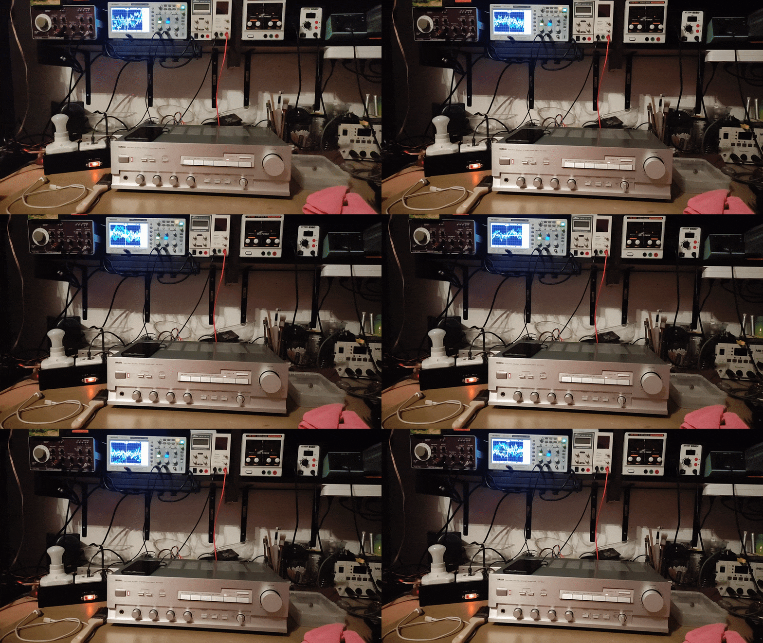
So I first started with a 60W bulb in the dim bulb tester and after turning it on the click from the relay could be heard. Great! So it looks like getting rid of the dry / old joints and removing the corroded resistor leg and links fixed the issue. The main culprit probably was the rotted through leg of that one resistor, afaik that's directly related to the protection circuitry. I then proceeded to hook up an old phone and looked up a 1KHz sine wave video to use as a tone generator. I felt this was easier for the moment than interfacing my crappy Toellner waveform generator (can be seen in the top left corner of my shelf next to the scope) to the RCA input of the amp. I admit was lazy and I had setup the MBO sound system that I inherited from my grandparents just a couple of minutes before so everthing was easy to connect. Anyway at first I was confused that the volume was so low, but that was probably due to the current limit of the dim bulb tester. CD direct however made the signal much louder on my headphones I don't know why. I also hooked up my digi scope to the speaker outputs and was again confused by the oscillating second channel but turns out it was just me being to stupid to set up the scope correctly and poor connection on the probes.
HmlOskt.jpg

97ZjP1k.jpg

Probe arrangement.
gQNp1I2.jpg

Poor mans tone generator.
tEFMNGC.jpg


There is still a bit of hum so I get the cover back on but I do not know if that helped that much. Anyway it seems like the preamp board is prone to vibration and I suspect that this is either more cold joints or more likely dirty switches. Down below is a picture of a distorted sine wave from the speaker output that I could also hear in on the headphones. So it's in the preamp already and the amp is just outputting that signal to the speakers.
6xg64aF.jpg


Does anyone know how to clean the input selector switches? Sure, yeah, washing with deoxit or similar I guess. I got Kontakt 61 (Contact cleaner) and Kontak WL (Washing Liquid). The switches look quite well encapsulated and I don't really want to open them if I don't have to. Any hints?

Anyway that's all for today.

Cheers!
 
I don't know what they look like. I've tried carburator cleaner, isoprophyl alcohol, deoxit, nail polish remover...for stubborn pots; and have had to eventually disassemble them, finding a gelatinous goo, or an oily-black carbon requiring scrubbing with a brass brush. Even drilling a small hole for solvent spraying, has not helped. Have a pic? Lol.
 
Well I did a pass of Kontak 61 but didn't turn off the amp so that probably wasn't so smart, idk. Anyway at first I had some issues and the latching of the switches got worse but then I left the more aggressive Kontak 60 to work over night and it was mostly fine afterwards. All the cans are expired, lol. I found some super old Kontakt WL and the cans didn't have any pressure left. Anyway I washed the switches with that and now waiting for it to evaporate. I think it will be fine. Most of the noise is gone now. Haven't washed the potentiometers yet but they are mostly quiet now so I don't see the need for doing this. I also used compressed air to work in the Kontakt WL some more and a syringe with a needle to directly apply it into the switches from the front. Meh ... time will tell if this issue resurfaces but as far as I know it will resurface. Just a matter of time. I really dread the day when I have to take these switches apart but in any case I am not sure how much usage that amp is going to see anyway.

YBhLorD.jpg

ljeexfx.jpg


I am also considering taking out the preamp board and giving it a good rinse but that would be mostly cosmetics at this point.

So what's probably left is to hook up some real speakers and see how it behaves. So far I've only done testing via the headphones but the speaker outputs on the scope seem to measure fine at the moment. Maybe I will also go through the service manual to see if it's still adjusted to spec (idle current, etc.).

Cheers!
 
Last edited:
So I tested the amp on some speakers and it seems to work well now. I went on to check the idle current and it seemed a bit high at roughly 27mV and 21mV on both channels respectively. Don't mind the two multimeters in parallel, this was intentional to check which one had the better resolution (it's the Fluke - I've forgotten this over the years).
m6IPcsI.jpg

7Lmirti.jpg


The service manual states 10mV +/-2mV for the idle current measurement. So anything between 8mV and 12mV should be fine. I've adjusted the values to 10.55mV an 10.44mV which was the best I could do with the sensitive single turn ports. I considered replacing them for 10 gang trim pots but I left it stock for the moment.
tY6Uz0v.jpg


I am not sure if I did anything wrong but the values seem to drift around a little. After some listening to music I ended up with 12.60mV and 10.34mV. Not sure what's going on here. I wonder >when< the measurement should be carried out. I would assume after the amp has reached thermal equilibrium but that would just be my guess. The service manual just states "measure under no input or load condition" and that is what I did and after some warmup / stabilization of the values. I disconnected the speakers (via the switches) and removed the input RCA plugs. Tone generator still hooked up to the inputs in the picture but the values are for the moment at what's shown in the picture. They will probably change again after listening to some music even if brought back to the no load / no input condition again. Hmm idk. It's probably fine.
Gh4MbiO.jpg


And that's all for now. Guess I will reassemble the amp now.

Cheers!
 
Idle current seems to stabilize at 10.60mV / 10.80mV or there about when warmed up. So I went on to clean the pots on the front. After all the bass tone pot was noisy. DC at the speakers seems to be R 40mV / L 80mV. Not too great but also not an issue according to some forums posts that I've looked at. There is no way to adjust this inside the amp anyway.

PuYkQED.jpg

zbKUf6I.jpg

hjOPX8m.jpg

he9JJoe.jpg

Z88dyUb.jpg


So I am considering this fixed and I got off easy. No defective components really besides the rotted through resistor and some links. Haven't testes phono though since I don't really have a phono record player.

Okr2iR7.jpg

PXL-20221114-174532626-sc35.gif


Cheers!
 
see what you mean with the pots being sealed. standing the unit up with the rear as a base, and with the pots pointing up, one could drizzle deoxit into them. nice job!
 
Deoxit is quite expensive where I live (25-30 Euro) and I had some similar contact cleaners at hand which seem to have worked but then again in the German forums concerning HIFI there are proponents and opponents of contact cleaners in general as the issue tends to come back over time. Taking apart the switches / pots and hand cleaning / greasing them seems to be a better solution but considering that this unit isn't really that rare I opted for the less time consuming way to get the pots and switches noise free again. Also I fear that I will break more stuff if I take the switches / pots apart down to that level.

The pots themselves aren't sealed. The opening is just on the bottom of the pots and not visible in the pictures. The input switches however don't seem to have an opening to spray contact cleaner in them so I sprayed / injected it directly into the lever crevices.

I've noticed that my current bedroom TV / computer amp (Yamaha CA-V1) is also showing some sings of it's age again (one channel is louder than the other sometimes, relay or switch issues most likely) so I swapped it for the AX-500 now. Refreshing the Yamaha CA-V1 will probably be my next effort but I will make a new thread for that.
 
Idle current seems to stabilize at 10.60mV / 10.80mV or there about when warmed up. So I went on to clean the pots on the front. After all the bass tone pot was noisy. DC at the speakers seems to be R 40mV / L 80mV. Not too great but also not an issue according to some forums posts that I've looked at. There is no way to adjust this inside the amp anyway.

I bet your unit has differential pair transistors to set DC offset. Those need to be matched to get even results on left and right and may also lower the DC at speaker outs. I have not looked at the schematic to identify said transistors.

Nashou
 
That's what I understood from reading various German and English forum posts as well. If there is no adjustment via pots then you need to match the semiconductors and if possible also thermally couple them toghether.

Here is the Full schematic some nice Polish person put together. Much easier to read than the separated sheets.
Bxli0v2.jpg


To be honest I don't know too much about the various stages in BJT power amplifiers. I've learnt how a complimentary amp consisting of two BJTs works, and probably could refresh my memory on that but I have no idea what the various magical stages before the power transistors pairs do. Voltage gain and current gain something something but no idea how to spot which part does what. That's over my skill level currently.
 
Last edited:
That's what I understood from reading various German and English forum posts as well. If there is no adjustment via pots then you need to match the semiconductors and if possible also thermally couple them toghether.

Here is the Full schematic some nice Polish person put together. Much easier to read than the separated sheets.
Bxli0v2.jpg


To be honest I don't know too much about the various stages in BJT power amplifiers. I've learnt how a complimentary amp consisting of two BJTs works, and probably could refresh my memory on that but I have no idea what the various magical stages before the power transistors pairs do. Voltage gain and current gain something something but no idea how to spot which part does what. That's over my skill level currently.
Well done! Thank you very much for sharing the repair process of your amplifier. I just bought a pair a few days ago, not sure if they are fully working, but they certainly deserve good cleaning.

I am not sure if the capacitors in them are any good but I have a variac so I am going to power them up slowly.

I wonder if the sound quality would improve if I mod the PSU by canibalising the transformer from one of them such that each channel will have its own transformer, then buy a bigger transformer for the other.

If it is at all possible I would like to increase the biasing voltage (without adding additional heatsink and output transistors) to see how it will play out.
 
Back
Top Bottom