• The move to the new server is done. There are some software and database maintenance updates in process. This has us passing the hat around to help out. We appreciate any donations. Seriously, even a dollar helps. The payment page may be found here - https://www.audiokarma.org/support.html

Yamaha B-6 Repair attempt and then we'll see...

I like the idea of replacing the output transistors with resistors to test the repairs of the amplifier. @Nashou66 used 2 watt 470 ohm resistors in his B-6 to do this.

Is this a good idea? How is the right resistance for this determined?
It works fine, I use 470 to 560 ohm for this job specifically . I determine which ones to use depending on if I can find them on my messy bench :D
 
Never considered doing that, one thing to keep in mind is at some arbitrary point, the output transistor collectors are going to switch to the high voltage rails and that seems to be when the party happens from what ive seen as my HV switching transistors have been replaced on both sides on mine… I haven’t got there with mine yet but I was hoping to run it with no load and hopefully they switch over still?

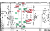
Other than different rail switching transistors, I also found these 2 resistors had been changed from 150ohm to 1.15k ohm. Haven’t worked out “why” yet…

I changed those resistors also and raised them :)

View attachment 3400470
I wouldn't keep the resistors installed and try to drive it with a signal. Just want to verify that I found all the failed parts in the debris field and try to avoid blowing any more output TRs up. I have also read about increasing the emitter resistors up to 100 ohms as well, but in this case pulling the outputs until the rest of the amp looks good seems like a great tactic.
 
Other than different rail switching transistors, I also found these 2 resistors had been changed from 150ohm to 1.15k ohm. Haven’t worked out “why” yet…

I changed those resistors also and raised them :)

View attachment 3400470

Yeah, that is an interesting situation to weed through. I'm pretty sure mine has 150 ohm resistors. I have been paying most of my attention to the power supply so far, but will take a harder look at the main board tonight.
 
Yeah, that is an interesting situation to weed through. I'm pretty sure mine has 150 ohm resistors. I have been paying most of my attention to the power supply so far, but will take a harder look at the main board tonight.
The power supply definitely needs a lot of attention. I changed all the 2sa777 / 2sc1815 transistors in mine last night just incase and the voltages are spot on. The test point for the opto is so dam vague luckily I found a reference on a german forum…
 
Chill night listening to King Buffalo testing components. Not completely through it yet, but here is the debris field so far...
1736998543738.png

The victims so far...
1736998684151.png
 
Interesting you have one of those white fuse resistors gone also (cool devices), mine had one of those changed also, Ive changed them all to 22ohm 1W metal films now as I blew one out messing with the pre drive board. Im definitely seeing some similarities around the rail switching area with parts that were previously replaced in mine. Didnt realise the bias test point was after that 150ohm resistor so it may have been done to limit the bias drive as my trimmers are near maximum.
 
Interesting you have one of those white fuse resistors gone also (cool devices), mine had one of those changed also, Ive changed them all to 22ohm 1W metal films now as I blew one out messing with the pre drive board. Im definitely seeing some similarities around the rail switching area with parts that were previously replaced in mine. Didnt realise the bias test point was after that 150ohm resistor so it may have been done to limit the bias drive as my trimmers are near maximum.
1W is not safe I think, it should be 1/4 watt . Those are fusible resistors .

On the bias adjust, were you able to adjust to the 2.5mv? I can only get to 1.5mv .

@Asmodeus2112 if your rail switching transistors are good you can use them to replace the outputs and go with sankens ,linked in my thread, for the rail switching.

Also you said you changed the 150 ohm's , did you go to the 1.15k value? What was in there originally? I can not remember if I needed to change mine or not .
Its just temporary ill put in some 1/2 watt when they arrive but either way they’re not fused so its still dangerous either way. I was going to put in some of those tiny fuse things in series also (maybe later) I already had one resistor flare up so I know what happens haha, I always elevate them off the PCB though.

I can get 2.5mv and its stable, but it is near the end of the trimmer adjustment. The B-6 does not appear to develop any bias until it heat up then the adjustment will be within range. I think those resistors might be related to it as I tried a different value in each side and getting different trimmer adjustments now.

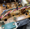
Whoever was in there before added a 1k resistor in series with the 150ohm stock resistor in all 4 places. Ill try going back to 150ohm and see if the adjustment moves again once the power supply is done on mine also, need to laser cut a sil pad for the triac then Im done in there.

Will check out your rail switching stuff also as im curious about that area…
oh, ok so there is basically 1.15k resistance there now. Let me know how the adjustment goes once you have only the 150 ohm restore in there. I wonder if the SM has it wrong. I wish the SM also had a parts list . The one I have does not, I like to check the schematic to the parts list as there are often many mistakes.

Athanasios
I think 150ohm is correct, says it in the service manual parts list also. It was added by someone later but could also be a service bulletin as the way it’s twisted together looks like something Yamaha service would do… I have the full parts list from HIFIengine. Regions are different also
 
Lucky me, somehow a broken B-6 ended up on one of my benches. For fun and the company I thought I would create a thread and post my progress as I work my way through this. Hopefully y'all can share some of your wisdom about the B-6 as I go as well.
View attachment 3399927
View attachment 3399928
View attachment 3399929
View attachment 3399930
I was gonna bye one but Xray Tony had so much trouble he scared me off........said he could not set the bias before it burn up or something to that effect...THEN he gave up...........its been awhile!
I had already bought a service manual!
 
Last edited:
I was gonna bye one but Xray Tony had so much trouble he scared me off........said he could not set the bias before it burn up or something to that effect...its been awhile!
Either he had something wrong or something else was going on because it isn’t that bad in my experience so far, other than not being able to use a dim bulb or variac. The adjustments in the power supply that he said were really unstable and want to run away have been the opposite for me. You don’t even have to connect the rest of the amp to the power supply really to test it.
 
Either he had something wrong or something else was going on because it isn’t that bad in my experience so far, other than not being able to use a dim bulb or variac. The adjustments in the power supply that he said were really unstable and want to run away have been the opposite for me. You don’t even have to connect the rest of the amp to the power supply really to test it.
He gave up, but someone here fixed one , but I think they said B6's are hard to work on......kinda hard to get to all the parts ..etc........and maybe hard to get all the right parts....That's another reason I stopped the buy, I wanted it bad...............I'll just read & wish...........
 
@Asmodeus2112 if your rail switching transistors are good you can use them to replace the outputs and go with sankens ,linked in my thread, for the rail switching.
YES, that is the plan of record. Although the owner of this amp may want to try to locate some pulls or NOS originals. (Long story, but I have a deal with the owner that he finds and buys interesting projects and I work on them for cost plus a very small charge. I am not doing this professionally, but as a hobby. I have way too many components already, so this deal allows me to continue to progress as a tech while mitigating the cost and not continue to grow the stack of gear that the wife does not particularly approve of...)
 
@Asmodeus2112 if your rail switching transistors are good you can use them to replace the outputs and go with sankens ,linked in my thread, for the rail switching.

I have only done a quick search, but the Sanken MT-200 you used may only be available from questionable sources. The alternative would be to find a suitable TO-3P replacement similar to what @WCGW has in his amp. There are various TO-3P to MT-200 adapters out there like the super cool but probably overkill for this application ones from hoppesbrain, or less expensive adapter plates like these. It would be good to know what kind of power the rail switching TRs run at and if any of the TR characteristics of the original Toshibas matter.
1737057663108.png
 
Might not be the end of the world anyway as the interface plate might be big enough to drill and tap a new hole for a different package. Not ideal though. I almost did it for mine as the outputs are from different years. Could turn them 90deg also like mine but man thats a lot of work with wiring haha

Cannot believe yamaha paint the interface plate… Ditching all those micas was the best thing I did on mine as there was definitely stray current leaking through.

Not sure about the rail switching as I didn’t fit the ones mine has, just relocated them. They don’t seem to run very hot as mine were floating in the air :(
 
Last edited:
Back
Top Bottom