• The move to the new server is done. There are some software and database maintenance updates in process. This has us passing the hat around to help out. We appreciate any donations. Seriously, even a dollar helps. The payment page may be found here - https://www.audiokarma.org/support.html

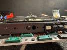
Yamaha B-6 Repair attempt and then we'll see...

On the Filter cap board are a bunch of R's that get hot and scorched the board, some of mine were way off value .
Replace with metal film and raise them off the board like this.


52215223034_95a16ae88e_b.jpg
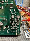
Interestingly, these resistors on the unit I am working on do not seem to have gotten as hot. some evidence of heat on the solder, but not too much evidence on the resistor bodies and PCB.
1738018123237.png


Solder on that cap is prior to me work.
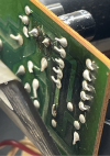
1738018160666.png
 
Interestingly, these resistors on the unit I am working on do not seem to have gotten as hot. some evidence of heat on the solder, but not too much evidence on the resistor bodies and PCB.
View attachment 3411936


Solder on that cap is prior to me work.
View attachment 3411937
Definitely lift them if you’re replacing resistors, plenty of heat there.

Side note… Replacement OMRON relay is too tall also, trying to work out a solution :whip:

IMG_5052.jpegIMG_5053.jpeg
 
Last edited:
Yes, of course. Just noting the condition of this unit. At the end of the day, I don't think the B-6 I am working on say a lot of use.
Looking closer at that image, it looks like the bottom 2 resistors are cracked also…

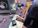
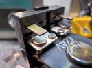
I ended up taking my relay apart, seems Yamaha’s quenching magnets actually do work and the contacts appear excellent after cleaning… It may be possible to fit an OMRON by shimming the PCB but its a lot of messing around…

IMG_5066.jpegIMG_5067.jpeg
 
If you can make MT-200 devices fit, would 200w 2SA1494/2SC3835 be overkill for this amp repair?

:beerchug:,
James
The original Toshibas are higher ft at 60 and 80 MHz. I don't know what is really needed, but I have been looking for the highest spec I can find. Seems like higher frequency modern TRs for Audio are in the 30-40 MHz range.
 
The original Toshibas are higher ft at 60 and 80 MHz. I don't know what is really needed, but I have been looking for the highest spec I can find. Seems like higher frequency modern TRs for Audio are in the 30-40 MHz range.
Well, if you need 4 pairs of them you might want to PM me.

:beerchug:,
James
 
Last edited:
I just bought 4 pairs of 2SC2922-G + 2SA1216-Y from Amps labs as spares . He said he is soon taking them down because he's building an amp project using them for his site.

Id get some guys before they are gone.

Athanasios
 
The original Toshibas are higher ft at 60 and 80 MHz. I don't know what is really needed, but I have been looking for the highest spec I can find. Seems like higher frequency modern TRs for Audio are in the 30-40 MHz range.
The higher ft numbers matter when the transistor is being used in higher frequencies (HF, VHF, etc.), for audio frequencies they don’t really matter as long as they’re reasonably high. Many of these transistors were also targeted toward the high frequency transmitter markets, hence the high ft specs.
 
From what I saw on a german forum, the B-6 bandwidth goes out to about 100Khz and 230W/pc. I’ve made it past 200Wpc so far, the B-6 seems like typical Yamaha with vanishingly low THD numbers and clean sound.

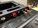
Side note, banana sockets are possible, finally finished my side quest tonight

IMG_5149.jpegIMG_5151.jpegIMG_5154.jpeg
 
Alright, I received parts and replaced what was damaged. I put 470Ohm resistors in place of the outputs. Powered it on and no smoke, and the protection light goes out. So far so good. Contemplating next steps.

I think I am going to see if I can adjust the PSU voltages as it is. Then sub in the replacements I have for the power rail TRs and test. If all goes well put the Toshiba outputs in. If all goes well I can call this amp repaired and then turn my attention to restoration.

1738814971873.png
 
Alright, I received parts and replaced what was damaged. I put 470Ohm resistors in place of the outputs. Powered it on and no smoke, and the protection light goes out. So far so good. Contemplating next steps.

I think I am going to see if I can adjust the PSU voltages as it is. Then sub in the replacements I have for the power rail TRs and test. If all goes well put the Toshiba outputs in. If all goes well I can call this amp repaired and then turn my attention to restoration.

View attachment 3419643
Yeah see how the PSU adjusts, I swapped out all the transistors in mine but they’re easy replacements. Use the square pads for correct measurements (assuming ur region is the same), the manual is super vague on this…

IMG_4868.jpeg

The rail switching transistors on mine were an excellent sub, don’t really get hot, ran mine to 220Wpc @ 0.003% pulling 1050W no issues.

Best advice would be to spend a lot of time on the pre drive boards as my guess is that seems to be what takes everything out…

Some other resources that came in handy:


This one will fit. Schrack PT270024.
Ended up using the stock relay, the bifurcated contacts put down better numbers than the newer OMRON relay. Contacts were excellent after cleaning, those quenching magnets seem to actually work but thanks for sharing it also, haven't heard of that one :)

This is the one I used and it fit fine Just remember to move the magnets from the original to the new one .


Athanasios
That's the one I used but its too tall, presses down on the PCB when you try to refit the bottom cover.

An observation I made: The DC offset was rather unstable, floating around +/- 25 mV. After replacing all Zeners and Diodes on the predrive pcb it is stable now.

Ive seen about 15mV swing on both sides after replacing the dual transistor packages in open air but it is very very thermally sensitive also. Makes sense though as the pre drive is heat stressed to hell and back, what diode subs did you use?
 
Last edited:
Back
Top Bottom