• The move to the new server is done. There are some software and database maintenance updates in process. This has us passing the hat around to help out. We appreciate any donations. Seriously, even a dollar helps. The payment page may be found here - https://www.audiokarma.org/support.html

Yamaha B2 Lateral MOSFET

Some measurements, laptop with REW and Focusrite Solo as source, another laptop with REW and Focustite 2i2 for measurement, to avoid ground loops.
8 Ohms load, 2200 uF capacitor in series to protect the input of the Focusrite if things goes wrong. Did my best to calibrate everyting before each measurement, but when relying mostly on variable attenuators in the Focusrites, it should to be taken with a grain of salt. Some artefacts at 20 kHz, not coming from the B2.

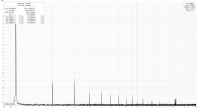
1 k, 1W
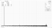
b2L 1k 1w.png
1k, 50 W
b2L 1k 50w.png

1k, 100W
b2L 1k 100w.png

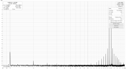
IMD 19+20 k, 1W
b2L 19+20k 1w.png

IMD 19+20k, 30W
b2L 19+20k 30w.png
 
Looks good. :thumbsup:

B2 SM adjustment procedure calls for THD < 0.02 at 30W into 8Ω, so you’re well under that, beside, anything under 1% (or even somewhat higher) is actually inaudible anyway (these were marketing ploys to sell products back in the 70’s and 80’s).

I sometimes use REW + Roland Quad-Capture for both source and measurement, haven’t encountered ground loop issues yet. Fewer parts to calibrate.

Enjoy :music:
 
Some measurements,

Some awesome work going on here and thanks so much for sharing it! :thumbsup:

Thirty some years ago the very first B-2 I had a chance to own was modified to use Hitachi TO-3 laterals. The seller wouldn't let me test it which didn't give me a warm and fuzzy so I decided to take a pass on it and wait for a V-FET 1 to come along ... :)
 
Some awesome work going on here and thanks so much for sharing it! :thumbsup:

Thirty some years ago the very first B-2 I had a chance to own was modified to use Hitachi TO-3 laterals. The seller wouldn't let me test it which didn't give me a warm and fuzzy so I decided to take a pass on it and wait for a V-FET 1 to come along ... :)
Thank you! :D

Would be a dream to have a B-1 someday :bowdown:
 
Some measurements, laptop with REW and Focusrite Solo as source, another laptop with REW and Focustite 2i2 for measurement, to avoid ground loops.
8 Ohms load, 2200 uF capacitor in series to protect the input of the Focusrite if things goes wrong. Did my best to calibrate everyting before each measurement, but when relying mostly on variable attenuators in the Focusrites, it should to be taken with a grain of salt. Some artefacts at 20 kHz, not coming from the B2.

1 k, 1W
View attachment 3790647
1k, 50 W
View attachment 3790649

1k, 100W
View attachment 3790650

IMD 19+20 k, 1W
View attachment 3790652

IMD 19+20k, 30W
View attachment 3790653

very nice!
The THD at 1W looks lower than at higher power. Is that what I am seeing? It usually is the other way around.
I am also pleasantly surprised to seeing that the unit is pushing 100wpc out of a single pair of output devices :beerchug:


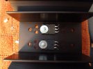
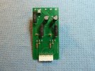
Some more pics of the PCB for the outputs. Components may differ between the pics, made quite some changes back and forth to get things right. :)

View attachment 3791218View attachment 3791228View attachment 3791220
View attachment 3791225
View attachment 3791227

I appreciate the creativity. Very nice and effective setup!!

One quick question: do those lytics need to be located towards the top of the board? Heat rises. How much heat are they seeing if you get the heat-sinks toasty? Can you move them towards the bottom, below the transistors and the source resistors?
 
very nice!
The THD at 1W looks lower than at higher power. Is that what I am seeing? It usually is the other way around.
I am also pleasantly surprised to seeing that the unit is pushing 100wpc out of a single pair of output devices :beerchug:


I appreciate the creativity. Very nice and effective setup!!

One quick question: do those lytics need to be located towards the top of the board? Heat rises. How much heat are they seeing if you get the heat-sinks toasty? Can you move them towards the bottom, below the transistors and the source resistors?
Yes, the low distortion at 1W suprises me too, but the simulation shows same behaviour (LT spice log below) :idea:
The ECW20N20/20P20 are dual-die, so two devices in same casing, good for 16A, used them to save space :) Amp clips at 132W.
Bias at aprox 225 mA, divided by two dies in each output device, around 110 mA per device, the output should have leaved class A at 1W, which would explain the low distortion otherwise. Or have I got the math wrong..?

I tried to move the lytics down when doing the layout, but could not find a working solution then, thought it would the first version and fix this in later PCB, but I never got to v.2 :) Heatsinks never rises above 40 degr. C, even when played pretty loud :music:

1W
Sim 1k 1W.png

100W
Sim 1k 100W.png
 
Could you post your LTspice .asc file? My first thought would be that this couldn't possibly work, so I want to see why I was wrong.
 
I'm thinking there'll a few more B-2's finding new life thanks to your generosity in this thread.

Will you be making any of your adaptor boards available? :naughty:
 
I see that you already had posted the .asc file. Thankyou! However, I'm now wondering about the placement of caps from gate to drain on the laterals. I don't think I have ever seen that before. Can you explain what led you to that?
 
I see that you already had posted the .asc file. Thankyou! However, I'm now wondering about the placement of caps from gate to drain on the laterals. I don't think I have ever seen that before. Can you explain what led you to that?
I had problems with oscillation when doing stability tests on the amp, probably caused by the long traces from drivers to the laterals. Tried a lot of ways to get rid of it, but nothing helped, finally found a post here where someone used this method to handle stray capacitances. Don't remember the theory behind it, but it worked great.
 
What is the idle current? I see you kept the original value 0.22 ohm source resistors which were originally shared by two devices.
Bias at aprox 225 mA, divided by two dies in each output device, around 110 mA per die, more info in post #28 :)
Yes, I stayed with the 0.22 ohms, my thought was that everything contributes to the sound signature and wanted it to stay as close to original sound as possible.
 
Bias at aprox 225 mA, divided by two dies in each output device, around 110 mA per die, more info in post #28 :)
Yes, I stayed with the 0.22 ohms, my thought was that everything contributes to the sound signature and wanted it to stay as close to original sound as possible.
missed it :)
50mv bias is well in the middle as long as the thermal transfer is effective. Also nice of having a dual die device and not needing to worry about matching on each channel.
How closely matched is your N and P? The THD tells they are very closed matched, so I guess the real question is how many transistors did you have to go through to find P&N close sets?
 
missed it :)
50mv bias is well in the middle as long as the thermal transfer is effective. Also nice of having a dual die device and not needing to worry about matching on each channel.
How closely matched is your N and P? The THD tells they are very closed matched, so I guess the real question is how many transistors did you have to go through to find P&N close sets?
Actually I only bought two P and two N, enough for two channels :) , so no matching at all, thought I would do fine tuning at a later stage.
Both channels measures very close to each other.
 
Actually I only bought two P and two N, enough for two channels :) , so no matching at all, thought I would do fine tuning at a later stage.
Both channels measures very close to each other.
Just curious here since it's been a couple of weeks now. Is the B-2 still going strong? May I ask how many play hrs. the laterals have on them by now?

I have 10 pieces of each of those laterals that I bought when they were first discovered 10+ years ago by DIY'ers on another forum. I'll be damned if I can find them in amongst all of my other treasures I have. :rflmao:

Also, 15 years ago my best friend and V-FET lover MC12'ed the B-2.. It took him a while to work out the V-FET models but he came up with some very reasonable facsimiles thanks to Michael Rothacker's work on that other forum. We had lots of fun discussing everything from the PS to the output stage. I was very lucky to have him as a friend for 50 years or so until the cancer got him a few years ago.

Sadly, it all happened very suddenly so I didn't have a chance to get the MC12 files before his sister and husband inherited his PC which they later scrapped. That said, I'm pretty sure I have a jpg of the circuit somewhere ...
 
Back
Top Bottom