• The move to the new server is done. There are some software and database maintenance updates in process. This has us passing the hat around to help out. We appreciate any donations. Seriously, even a dollar helps. The payment page may be found here - https://www.audiokarma.org/support.html

Yamaha C-70 Project

sonavor

Active Member
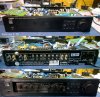
My first Yamaha preamplifier was a C-70 that I bought new in 1983. I purchased it along with an M-70 and a pair of NS2000 speakers. It was the first time I spent that much on a stereo system but I was very happy with the results. When I got into restoring and collecting audio equipment a few years back I acquired some other Yamaha preamps. As I got those restored I stopped using my C-70 for quite some time as it was starting to show its age.
With some recent repair issues needed on my C-85 and C2a preamps I decided it was time I restore the old C-70. Although it always ran hot, it was a great performer.

So here is the start of my C-70 restoration project. My plan was to replace the electrolytic capacitors, re-solder connections and replace the trimmers.
yamaha_c70_restoration_001.jpg
 
Last edited:
Register to hide this ad
One area of concern on the Yamaha C-70 is the SW104 solenoid/relay switching device which is responsible for making the actual signal routing when you select a function from the C-70 front panel. I had already taken the SW104 unit out, cleaned and lubricated it a few years back so I felt I didn't need to do that again. If your C-70 is having strange function switching problems this unit is the likely culprit.
yamaha_c70_restoration_002.jpg
 
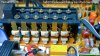
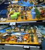
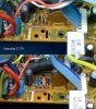
The logic for the function switching is on the Tone Control 2 PCB. This board also has three resistors - R859, R860 and R863 that appear to provide the load to manage the C-70 Power On lamp. The large, white resistor is R860. It is 390 Ω and gets very hot when the C-70 is on. The PCB has darkened over time around and underneath this resistor due to the heat. None of the electrolytic capacitors on this board are in the signal path. I will replace them with 105°C high reliability capacitors (Nichicon usually). This board has a ton of 2.2uF capacitors and I will replace all of them with WIMA Polyester caps.
yamaha_c70_restoration_003.jpg
 
Here is a picture showing the C-70 front panel control buttons and the Tone Control 2 board. It also shows the C-70 power lamp connection to the Tone Control 2 board. I always liked these type of function buttons. They look good and perform good (as long as you maintain SW104).
yamaha_c70_restoration_004.jpg
 
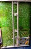
To start in on the recap and re-soldering it is tempting to just remove the bottom plate of the case and do everything that way. However, there is a big support bar underneath that makes de-soldering connections difficult. It is better to go the long route of taking apart the C-70 so you can pull the boards and do a good soldering job. Another reason to do this is the C-70 has a whole bunch of capacitors...so the job is a big one regardless. If I'm going to replace that many capacitors I don't want to come back later and do other things like clean switches and replace heatsink compound. Now is the time to restore everything that is easy to get to with the unit apart.
yamaha_c70_restoration_008.jpg
 
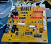
The first board I removed to work on is the Equalizer board. It has the phono equalization circuits on it.
yamaha_c70_restoration_009.jpg
 
Like a number of Yamaha audio components from the eighties, Yamaha used some sort of glue to secure large capacitors to the PCB. This glue does not age well and starts corroding other parts around it.
The 1000uF reservoir capacitors had this glue and as you can see badly corroded a jumper wire. I cleaned everything off and replaced the corroded parts.
yamaha_c70_restoration_011.jpg
 
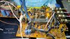
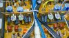
Here is a picture of that power supply area before the recap. The two power transistors (TR542 & TR547) are mounted to the large heatsinks for cooling. This area of the C-70 always got really hot.
yamaha_c70_restoration_005.jpg
 
Last edited:
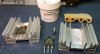
Inspecting TR542 & TR547 I could see that the heatsink compound was completely dried out. So I pulled those out, cleaned them up and applied new compound. This picture shows how dried out the original compound was.
yamaha_c70_restoration_013.jpg
 
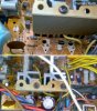
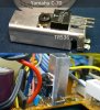
Transistor TR536 is also mounted to a heatsink. It is a smaller one but I decided to change the compound on it as well. When I removed that transistor and heatsink I found more corrosion from the Yamaha glue. I cleaned the area up and replaced the resistors and a diode.
yamaha_c70_restoration_015.jpg
 
For the rest of the recap I used the 105°C, low impedance, high reliability Nichicon caps for capacitors not in the signal path. For capacitors involved in the signal path I used Elna and Nichicon audio grade caps.
yamaha_c70_restoration_017.jpg
 
For the replacement of the C-70 adjustment trimmers, I used Bourns multi-turn trimmers. I use them quite a bit and like the finer adjustment they provide.
yamaha_c70_restoration_018.jpg
 
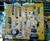
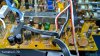
The C-70 Equalizer main board has two smaller boards (Equalizer2 and Equalizer3). They are also for the C-70 phono equalization circuitry. Here is what they were before the recap.
yamaha_c70_restoration_006.jpg
 
Here are the boards after the recap. I un-soldered and removed those two boards in order to replace the caps and trimmers on them.
yamaha_c70_restoration_020.jpg
 
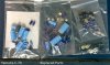
The C-70 had as many electrolytic capacitors or more than any other amplifier I have restored. Here are all of the replaced parts.
yamaha_c70_restoration_021.jpg
 
Back
Top Bottom