• The move to the new server is done. There are some software and database maintenance updates in process. This has us passing the hat around to help out. We appreciate any donations. Seriously, even a dollar helps. The payment page may be found here - https://www.audiokarma.org/support.html

Yamaha CA-1000 III (CA1010) left meter not working

wildmermaid7

Active Member
Hi guys

My CA-1000 III(CA-1010) Left meter not working. It was working fine before but not working anymore. I have checked the voltages for the left(ML) and right(MR) meters on the meter board and there is no voltage for the left, where as right has 3.3 volts coming in.
Any help would be much apperciated. I have also checked the coupler switch at the back, seems to be working ok.

thanks
 
Register to hide this ad
Use the schematic and carefully trace back the voltages on the meter board and see at which point you do have correct (give or take) voltages, maybe you’ll find the bad part. You can also compare with the working channel. Please be careful not to make any shorts, use mini grabbers or IC clips.
 
Use the schematic and carefully trace back the voltages on the meter board and see at which point you do have correct (give or take) voltages, maybe you’ll find the bad part. You can also compare with the working channel. Please be careful not to make any shorts, use mini grabbers or IC clips.
Thanks for that. I have checked the voltages and the board is receiving input voltage of 31 v .It's just that the voltage is not coming out for the left meter from the black box on the meter board.Not sure if that's faulty but voltage for the right is coming out from the same black box.
 
Thanks for that. I have checked the voltages and the board is receiving input voltage of 31 v .It's just that the voltage is not coming out for the left meter from the black box on the meter board.Not sure if that's faulty but voltage for the right is coming out from the same black box.
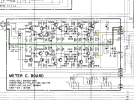
I don’t have this amp, all I have is the schematic for CA-1010, so I don’t know any black box. The MR and ML voltages you mentioned are highlighted below in yellow, do you have access to the rest of the circuit to see if Tr517, 515, etc. are functioning properly? Maybe someone who actually has this amp will chime in too regarding that black box …

6BC235B8-2C26-4952-A87D-7BB14D5FCDE8.png
 
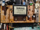
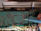
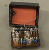
This is the black box on the meter board and there is no voltage coming out of the pin pointed by the screw driver, where as the the adjacent pin has voltage traced to the right meter.
 

Attachments

  • 16994553166135905597126336855112.jpg
    16994553166135905597126336855112.jpg
    107 KB · Views: 26
  • 16994553818231997833274991538286.jpg
    16994553818231997833274991538286.jpg
    93.1 KB · Views: 27
This is the black box on the meter board and there is no voltage coming out of the pin pointed by the screw driver, where as the the adjacent pin has voltage traced to the right meter.
Oh boy … looks like a proprietary Yamaha module, can it be opened? hermetically sealed? Wonder if someone like @mbz will have any info on this module. Meanwhile make sure the solder connections are good, a bit of reflow wouldn’t hurt. I’d reflow that whole board anyway.
 
Yes thats a bit concerning if there is a prob with the module.Where am I Gona source that :(.Will try a reflow though
If that’s the case, maybe a parts unit or a part on the bay, but I’m getting ahead of myself here. Check all the connections, it could easily be a connection issue.
 
clinic-audio would be the only one that could have yamaha documentation on the module.
See https://audiokarma.org/forums/index...eter-driver-pm-02-ig00136-help-needed.790426/
for the CA-2010 uses an IC while the CA-1010 is discrete albeit encased in "goop" Vaguely recall yamaha5000 also did some work in this area. Will do some more digging.

First step would be to verify the module is receiving signal, ie, not a switch issue. Press the switch between the meters, any reaction?
 
Yamaha5000 was working on a psu module not meter drive.
The easy fix is to find a parts unit. Possibly the CA-2010 module could be used or diy an IC based solution based on CA-2010.
More digging required...
 
clinic-audio would be the only one that could have yamaha documentation on the module.
See https://audiokarma.org/forums/index...eter-driver-pm-02-ig00136-help-needed.790426/
for the CA-2010 uses an IC while the CA-1010 is discrete albeit encased in "goop" Vaguely recall yamaha5000 also did some work in this area. Will do some more digging.

First step would be to verify the module is receiving signal, ie, not a switch issue. Press the switch between the meters, any reaction?
Thanks.Yes I was checking this thread and hats off to the guy who made this module.I guess I will have to go through this path if nothing fixes it.Pressing the switch,left meter no reaction,right meter yes.
 
Yamaha5000 was working on a psu module not meter drive.
The easy fix is to find a parts unit. Possibly the CA-2010 module could be used or diy an IC based solution based on CA-2010.
More digging required...
Not sure if I can find this part, even if I do it would be cost prohibitive.
 
I have reflowed all the pins of the module but no results.Module is getting the power as the right meter works fine.Thought to check the left meter itself, but no issues with the meter as it works when connected to right meter pins on the board.There is just no voltage coming out of the module for left meter
 
Being a bit perdantic... did you check for audio at the SL and SR pins on the meter board. You can do this by setting your meter to Vac say 2V scale, black probe connected to any black spkr connector and check that the readings bounce about in time with the music, compare L&R channels (white and pink wires). OK since audio is ok to the spkrs they should be ok...

Also check for VAC at R505 marked below
 

Attachments

  • R505.jpg
    R505.jpg
    124.2 KB · Views: 11
Being a bit perdantic... did you check for audio at the SL and SR pins on the meter board. You can do this by setting your meter to Vac say 2V scale, black probe connected to any black spkr connector and check that the readings bounce about in time with the music, compare L&R channels (white and pink wires). OK since audio is ok to the spkrs they should be ok...

Also check for VAC at R505 marked below
Thanks mate, i will check these and report back. I have tested the speaker outputs with 1KHz tone from the function generator and they all seems to be ok. But i will check it on the meter board as you directed. Thanks for the tip.
 
ciao a tutti scrivo in italiano per essere più chiaro possibile sul tema e problema del vu meter modulo komatsu IG00136, potete poi usare google translator come ho fatto io traducendo le vostre discussioni.
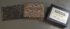
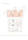
dalle 2 fotografie di wildmermaid7 ho visto che il circuito vu meter CA1000 III è uguale al CA2010
1) le tensioni da misurare sul modulo sono nel piedino 2 (-12V) e 8 (+12V) la massa al telaio GND
ho già parlato con lui, io ho ricostruito questo modulo perfettamente funzionante e simile all'originale, ho pubblicato il file gerber che pubblico anche qui.
2) bisogna aprirlo con cautela infilanto un cacciavite alle estremità e sperare che non sia immerso nella resina......
3) se anche il tuo è cosi come da fotografie il difetto potrebbe essere l'integrato JRC4558 o il transistor 2SC982/2SC1432, fare attenzione alla resina sul pcb da rimuovere per arrivare al lato saldature
sono disponibile a qualsiasi chiarimento.
 

Attachments

ciao a tutti scrivo in italiano per essere più chiaro possibile sul tema e problema del vu meter modulo komatsu IG00136, potete poi usare google translator come ho fatto io traducendo le vostre discussioni.
dalle 2 fotografie di wildmermaid7 ho visto che il circuito vu meter CA1000 III è uguale al CA2010
1) le tensioni da misurare sul modulo sono nel piedino 2 (-12V) e 8 (+12V) la massa al telaio GND
ho già parlato con lui, io ho ricostruito questo modulo perfettamente funzionante e simile all'originale, ho pubblicato il file gerber che pubblico anche qui.
2) bisogna aprirlo con cautela infilanto un cacciavite alle estremità e sperare che non sia immerso nella resina......
3) se anche il tuo è cosi come da fotografie il difetto potrebbe essere l'integrato JRC4558 o il transistor 2SC982/2SC1432, fare attenzione alla resina sul pcb da rimuovere per arrivare al lato saldature
sono disponibile a qualsiasi chiarimento.
Thank you @Ardensio for excellent and clear info, nice job indeed. :thumbsup::trebon:


@wildmermaid7 , better get that screw driver out to see if you can ‘carefully’ pry this thing open …
 
Back
Top Bottom