• The move to the new server is done. There are some software and database maintenance updates in process. This has us passing the hat around to help out. We appreciate any donations. Seriously, even a dollar helps. The payment page may be found here - https://www.audiokarma.org/support.html

Yamaha CA-1000 III (CA1010) left meter not working

Being a bit perdantic... did you check for audio at the SL and SR pins on the meter board. You can do this by setting your meter to Vac say 2V scale, black probe connected to any black spkr connector and check that the readings bounce about in time with the music, compare L&R channels (white and pink wires). OK since audio is ok to the spkrs they should be ok...

Also check for VAC at R505 marked below
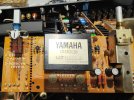
@mbz I have checked the speaker cables and they seem to be fine with voltages. As for the resistor r505 I am not sure which one is it on the meterboard since they are not marked as such. It maybe a resistor inside the module. I have checked the resistor values of all the resistors on the meter board as pointed by the arrows in the pic and they seem to be consistent on both sides. The only thing i havent checked are these two electrolytic caps. I can check them and see if they are the problem.
 

Attachments

  • IMG20231109180631.jpg
    IMG20231109180631.jpg
    157.6 KB · Views: 2
ciao a tutti scrivo in italiano per essere più chiaro possibile sul tema e problema del vu meter modulo komatsu IG00136, potete poi usare google translator come ho fatto io traducendo le vostre discussioni.
dalle 2 fotografie di wildmermaid7 ho visto che il circuito vu meter CA1000 III è uguale al CA2010
1) le tensioni da misurare sul modulo sono nel piedino 2 (-12V) e 8 (+12V) la massa al telaio GND
ho già parlato con lui, io ho ricostruito questo modulo perfettamente funzionante e simile all'originale, ho pubblicato il file gerber che pubblico anche qui.
2) bisogna aprirlo con cautela infilanto un cacciavite alle estremità e sperare che non sia immerso nella resina......
3) se anche il tuo è cosi come da fotografie il difetto potrebbe essere l'integrato JRC4558 o il transistor 2SC982/2SC1432, fare attenzione alla resina sul pcb da rimuovere per arrivare al lato saldature
sono disponibile a qualsiasi chiarimento.

@Ardensio you are the king ! This is extremely helpful. I am suspecting my IG00136 is the problem, there maybe some faulty part which is choking the voltage to the left meter.Even though right meter is working fine through it. I think i will just go through your solution as opening the module itself is just a waste and a pain in the lower portion. Can you confirm the parts list you have posted in your other thread ? or do we need any changes there as well. I hope everything is availble with Mouser or Digikey ?
 
@Ardensio you are the king ! This is extremely helpful. I am suspecting my IG00136 is the problem, there maybe some faulty part which is choking the voltage to the left meter.Even though right meter is working fine through it. I think i will just go through your solution as opening the module itself is just a waste and a pain in the lower portion. Can you confirm the parts list you have posted in your other thread ? or do we need any changes there as well. I hope everything is availble with Mouser or Digikey ?
If you’re lucky and can open the module, you may be able to just change an Op-Amp or a transistor … I think definitely worth a try, nothing to lose … it’s your call.
 
If you’re lucky and can open the module, you may be able to just change an Op-Amp or a transistor … I think definitely worth a try, nothing to lose … it’s your call.
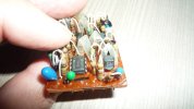
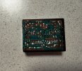
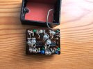
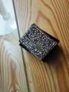
Thanks @Sparkplug i have managed to get it out without destroying it in just over 15 mins :) thanks to my precision heatgun and Hobby knife.
 

Attachments

  • IMG20231109203044.jpg
    IMG20231109203044.jpg
    120.7 KB · Views: 18
  • IMG20231109203050.jpg
    IMG20231109203050.jpg
    138.3 KB · Views: 18
Thanks @Sparkplug i have managed to get it out without destroying it in just over 15 mins :) thanks to my precision heatgun and Hobby knife.
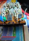
:thumbsup: Great job, well done.

Now you can test to see which part is bad, almost any of them can be replaced, with originals if need be! :biggrin:
Please report back your findings.
 
Last edited:
I think you need to power it up, maybe solder it back in? @Ardensio can confirm what’s the best way as he’s done it … then you can measure voltages on the ICs/transistors on the failing side and compare with those on the working side, identifying the bad parts.
 
Last edited:
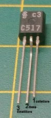
rispondo qui a tutti, il canale sinistro è quello dove ci sono i 6 pin lato pcb da saldare, quindi ti consiglio di rimuovere l'integrato e inserire uno zoccolino e sostituirlo, il riferimento del canale sinistro lo vedi dal condensatore verde e il transistor T-C982, di solito il guasto si verifiva sul ics 4558 ma potrebbe essere anche il transistor difettoso, questo ultimo bisogna fare attenzione perchè sono introvabili gli originali, io ho usato il modello BC517 ma vanno invertiti i piedini perchè il C982 ha i pin:
1 Emettitore, 2 collettore, 3 Base, mentre il BC 517 vedi la fotografia, comunque con il tester in modalità diodo è possibile misurarlo se c'è la giunzione su base-collettore e base-emettitore.
se non è chiaro ci aggiorniamo
 

Attachments

  • BC517 Siemens 3.jpg
    BC517 Siemens 3.jpg
    82.2 KB · Views: 6
  • 2SC1432-2SC982.gif
    2SC1432-2SC982.gif
    2.1 KB · Views: 6
rispondo qui a tutti, il canale sinistro è quello dove ci sono i 6 pin lato pcb da saldare, quindi ti consiglio di rimuovere l'integrato e inserire uno zoccolino e sostituirlo, il riferimento del canale sinistro lo vedi dal condensatore verde e il transistor T-C982, di solito il guasto si verifiva sul ics 4558 ma potrebbe essere anche il transistor difettoso, questo ultimo bisogna fare attenzione perchè sono introvabili gli originali, io ho usato il modello BC517 ma vanno invertiti i piedini perchè il C982 ha i pin:
1 Emettitore, 2 collettore, 3 Base, mentre il BC 517 vedi la fotografia, comunque con il tester in modalità diodo è possibile misurarlo se c'è la giunzione su base-collettore e base-emettitore.
se non è chiaro ci aggiorniamo
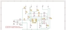
Thanks @Ardensio . I did check both the transistors in circuit across the three pins and they have similar voltages so i assume that the transistors are fine. I am not sure how to check the ICS 4558 if the one on my module its similar in pin configuration as per your schematic, is it possible to check it by reinstalling the module in the circuit ? i am thinking i should check pin 8 to the ground or is there any other pin i need to check ?
 

Attachments

  • Yamaha CA2010 schema IG00136 24-03-23-1 (1).jpg
    Yamaha CA2010 schema IG00136 24-03-23-1 (1).jpg
    45.9 KB · Views: 3
Last edited:
If the IC, NEC C4558, is the dual op-amp that I think it is, a direct replacement is:

The easiest way to power it up is to solder the module back in. Prior to that, and I think @Ardensio also mentioned, is to use 8-pin sockets for the op-amps so you can pop-in and pop-out ICs as necessary. You can leave the sockets in at the end, many commercial products have them as well, ICs are not so easy to take out and need some effort to be pried out.

The data sheet attached here, will show you the IC pin out, you should basically check the V+ and V- pins (4 and 8) to make sure they’re correct. Usually blown op-amps show irregular bias voltages. You can make a comparison between the bad and the good channels. If one is found faulty, better to change both, however, any of this will require recalibration of the meter too. Good luck.
 

Attachments

If the IC, NEC C4558, is the dual op-amp that I think it is, a direct replacement is:

The easiest way to power it up is to solder the module back in. Prior to that, and I think @Ardensio also mentioned, is to use 8-pin sockets for the op-amps so you can pop-in and pop-out ICs as necessary. You can leave the sockets in at the end, many commercial products have them as well, ICs are not so easy to take out and need some effort to be pried out.

The data sheet attached here, will show you the IC pin out, you should basically check the V+ and V- pins (4 and 8) to make sure they’re correct. Usually blown op-amps show irregular bias voltages. You can make a comparison between the bad and the good channels. If one is found faulty, better to change both, however, any of this will require recalibration of the meter too. Good luck.
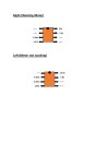
I have measured voltages on both IC's Pins in circuit and the results are in the diagram. As you can clearly see in comparison voltages on the left side are not consistent. There is something going on with this IC. So the options are to change both the IC's on this board or i just create another board as per Ardensio instructions. Changing IC on the original board would be a bit risky as i am not sure which component on the board has caused it to behave like this. Suggestions are welcome
 

Attachments

  • Right.jpg
    Right.jpg
    23.2 KB · Views: 5
I have measured voltages on both IC's Pins in circuit and the results are in the diagram. As you can clearly see in comparison voltages on the left side are not consistent. There is something going on with this IC. So the options are to change both the IC's on this board or i just create another board as per Ardensio instructions. Changing IC on the original board would be a bit risky as i am not sure which component on the board has caused it to behave like this. Suggestions are welcome
Your best course of action is getting this original board repaired, I’d keep making a new pcb as the last option. There’s no reason to throw this Yamaha board out, it just has some failing components.

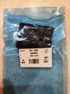
You can order a number of these ICs (they’re cheap, get 10) just in case another one goes bad (not very likely).

Based on your measurements, the supply voltages are consistent so if there’s IC damage, it’s not supply related. Also the transistors on that module, could you measure the cbe voltages on both channels for comparison? Eventually a more clear picture will emerge as where the fault is … we hope. LOL
 
Last edited:
tutto giusto quello che ha scritto sparkplug, difficilmente si danneggiano le resistenze, i diodi al germanio OA90 e i diodi switching che dovrebbero essere gli 1S1555, dalla scheda di wildmermaid7 è chiaro che c'è un difetto sui pin e credo che al 99% sia lui, concordo di sostituirlo sul pcb originale, sul mio CA2010 quando ho aperto la prima volta IG00136 ho trovato sostituito propio il 4558:cool: come si può vedere in fotografia.
 

Attachments

  • P1150417.JPG
    P1150417.JPG
    65.6 KB · Views: 12
tutto giusto quello che ha scritto sparkplug, difficilmente si danneggiano le resistenze, i diodi al germanio OA90 e i diodi switching che dovrebbero essere gli 1S1555, dalla scheda di wildmermaid7 è chiaro che c'è un difetto sui pin e credo che al 99% sia lui, concordo di sostituirlo sul pcb originale, sul mio CA2010 quando ho aperto la prima volta IG00136 ho trovato sostituito propio il 4558:cool: come si può vedere in fotografia.
Thanks. I will order the parts and repair the Yamaha board. Will install DIP sockets to make the IC removal easier incase of faults. Will update once i reinstall the module and see if everything works out.
 
Hello everybody. I'm looking for a VU meter for a Yamaha CA-810. I think one like the one you are fixing will also work. Do you know if anyone sells one? There are none on eBay. Thank you very much and my pleasure to greet you
Welcome to the forum @Isra, please start a new thread for your issue to avoid losing focus here in this one.
Good luck. :thumbsup:
 
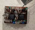
Success Gentlemen ! Changing the chips fixed the issue. Both my meters are working. Thanks to all you guys for your help specially @Sparkplug & @Ardensio.
Some pics of the modification and Meters.
 

Attachments

  • IMG20231116160601.jpg
    IMG20231116160601.jpg
    271 KB · Views: 8
  • IMG20231116160647.jpg
    IMG20231116160647.jpg
    258.9 KB · Views: 9
  • IMG20231116160721.jpg
    IMG20231116160721.jpg
    119.8 KB · Views: 10
  • IMG20231116161326.jpg
    IMG20231116161326.jpg
    228.8 KB · Views: 10
  • IMG20231116183147.jpg
    IMG20231116183147.jpg
    78.2 KB · Views: 10
Back
Top Bottom