

You are using an out of date browser. It may not display this or other websites correctly.
You should upgrade or use an alternative browser.
You should upgrade or use an alternative browser.
Yamaha CA-1000III Repair
- Thread starter joshcain
- Start date
Has the unit had any work done, recap etc...
Possibly you have a dc offset problem or the cap that's part of the mute timing is almost dead.
If you can use a multimeter....
Remove the base plate to expose the power supply/relay board. Near the (clear perspex) relay are 4 wires marked RO, RI, LI, LO (Right/Left IN/OUT)
Clip the red meter probe to RI and the black probe to chassis, set scale to 2VDC or... power on the amp and wait about 5 seconds for it to settle then read the meter, ideally 0mV, 10-20mV is fine More than 100mV is starting to be a problem.
Repeat for the LI pin/wire
If voltages are good then take a look/replace C403 (10uf/25V?), think it's one of the purple/lavender ones and known to fail, replace with low esr type like Nichicon UPW or...
Possibly you have a dc offset problem or the cap that's part of the mute timing is almost dead.
If you can use a multimeter....
Remove the base plate to expose the power supply/relay board. Near the (clear perspex) relay are 4 wires marked RO, RI, LI, LO (Right/Left IN/OUT)
Clip the red meter probe to RI and the black probe to chassis, set scale to 2VDC or... power on the amp and wait about 5 seconds for it to settle then read the meter, ideally 0mV, 10-20mV is fine More than 100mV is starting to be a problem.
Repeat for the LI pin/wire
If voltages are good then take a look/replace C403 (10uf/25V?), think it's one of the purple/lavender ones and known to fail, replace with low esr type like Nichicon UPW or...
Attachments


Sparkplug
Super Member
Does this happen with no input to the amp as well? Just the amp by itself. If no, try a different source to see if there’s any difference. , there may be an issue with your current input source. I recently tried a cheapish pre-amp with my B-50, and the B-50 took over 15 seconds to come out of protection, as opposed to usual 3 to 5. The pre-amp grounding is not solid.
If yes, it still happens all the same, well, @mbz already said it. I‘d set the DC offset voltage first before replacing C403. Somehow caps don’t usually go bad in Japan … unless abused.
If yes, it still happens all the same, well, @mbz already said it. I‘d set the DC offset voltage first before replacing C403. Somehow caps don’t usually go bad in Japan … unless abused.
Last edited:
I haven't had a chance to test with my multimeter yet, since I'm only at that house on weekends and I'm juggling numerous other higher priority home projects. One interesting note, though...
I powered on the amp, with no input (phono, receiver, etc. - all off), and it took about 4 minutes to come out of protect. I heard the relay engage at about 4 minutes. As noted before, then she worked like a champ and I played records for a few hours while I worked around the house.
Later in the day, I turned off the amp and killed the main house breaker while I did some electrical work for about 15 minutes. After about 15 minutes being off, I turned the amp back on. This time, it came out of protect in about 30 seconds, maybe even less.
It clearly operates differently when warmed-up vs. a cold start. I'm not sure what conclusion to draw from this but I thought it was worth noting. Are aged components more likely to behave differently cold vs. warm (or maybe fully discharged vs retaining some voltage)? Is there a cap who's discharge characteristics are off and affected in this way?
I will be back there in about two weeks and will take some voltage readings at the relay then, and report back.
I powered on the amp, with no input (phono, receiver, etc. - all off), and it took about 4 minutes to come out of protect. I heard the relay engage at about 4 minutes. As noted before, then she worked like a champ and I played records for a few hours while I worked around the house.
Later in the day, I turned off the amp and killed the main house breaker while I did some electrical work for about 15 minutes. After about 15 minutes being off, I turned the amp back on. This time, it came out of protect in about 30 seconds, maybe even less.
It clearly operates differently when warmed-up vs. a cold start. I'm not sure what conclusion to draw from this but I thought it was worth noting. Are aged components more likely to behave differently cold vs. warm (or maybe fully discharged vs retaining some voltage)? Is there a cap who's discharge characteristics are off and affected in this way?
I will be back there in about two weeks and will take some voltage readings at the relay then, and report back.

If voltages are good then take a look/replace C403 (10uf/25V?)

All, thanks for everyone's patience. I had a free weekend to do a deep dive on this project.
DC offset is .6v across right and left channels.
Voltage R1 to gnd is -19mV
Voltage L1 to gnd is 10mV
Board visually looks good, and it doesn't appear to have been recapped but some of you SMEs will know better than I.
So I'm leaning towards replacing C403 as a suspect component.
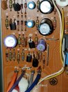
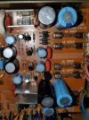
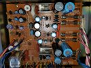
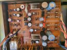
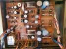
I've attached some photos here for review.
Thanks for any advice.
JC
DC offset is .6v across right and left channels.
Voltage R1 to gnd is -19mV
Voltage L1 to gnd is 10mV
Board visually looks good, and it doesn't appear to have been recapped but some of you SMEs will know better than I.
So I'm leaning towards replacing C403 as a suspect component.
I've attached some photos here for review.
Thanks for any advice.
JC
Attachments
-
 20240622_094726.jpg110.2 KB · Views: 5
 -
 20240622_094710.jpg154.4 KB · Views: 4
 -
 20240622_094656.jpg177.5 KB · Views: 4
 -
 20240622_094647.jpg160.4 KB · Views: 4
 -
 IMG-20240622-WA0003.jpeg100.8 KB · Views: 4
 -
 20240622_092607.jpg131.1 KB · Views: 4
 -
 20240622_092419.jpg150.6 KB · Views: 4
 -
 20240622_092323.jpg155.3 KB · Views: 4
 -
 20240622_092314.jpg138.4 KB · Views: 5
 -
 20240622_092302.jpg165.1 KB · Views: 5
On a side note, I did an in-circuit ESR test of C403 and it returned ~10uF and multiple tests seem to fluctuate between 10 and 25 ohms. Understanding that in-circuit testing is less accurate, I still noted it is within range.
Attachments
Sparkplug
Super Member
If by L1 and R1 you mean Li and Ri, then your DC offset seems fine. If you have two DMMs, connect them up and monitor these two voltages while playing music (using IC or mini-grabbers). See if at any point you get spikes causing protect circuit to kick in. Having a Max function would be of great help.
What did you mean by ‘DC offset across right and left’? Where did you measure 0.6V at? Please specify.
Have you checked/set the idle bias current at any point since your purchase? This is the voltage across TP1 and TP2 on the main board and is explained in the SM. It is adjusted through VR301 and VR302 for Normal and Class A operation. Be sure to follow the SM closely.
From the photos at least, your caps look to be in pristine condition physically. I wouldn’t change anything yet, maybe reflowing the solder joints would be a better starting point, especially around the power supply and protect circuit. I have never pulled a bad cap on any of my units purchased in Japan, ever.
Do not measure caps in-circuit. They’re often in parallel or series with other components which means you may end up measuring equivalent resistances. Best to test OOC.
What did you mean by ‘DC offset across right and left’? Where did you measure 0.6V at? Please specify.
Have you checked/set the idle bias current at any point since your purchase? This is the voltage across TP1 and TP2 on the main board and is explained in the SM. It is adjusted through VR301 and VR302 for Normal and Class A operation. Be sure to follow the SM closely.
From the photos at least, your caps look to be in pristine condition physically. I wouldn’t change anything yet, maybe reflowing the solder joints would be a better starting point, especially around the power supply and protect circuit. I have never pulled a bad cap on any of my units purchased in Japan, ever.
Do not measure caps in-circuit. They’re often in parallel or series with other components which means you may end up measuring equivalent resistances. Best to test OOC.
Was this when the music stopped playing, ie, amp going into protect?Voltage R1 to gnd is -19mV
Voltage L1 to gnd is 10mV
I measured DC offset at the speaker output.If by L1 and R1 you mean Li and Ri, then your DC offset seems fine. If you have two DMMs, connect them up and monitor these two voltages while playing music (using IC or mini-grabbers). See if at any point you get spikes causing protect circuit to kick in. Having a Max function would be of great help.
What did you mean by ‘DC offset across right and left’? Where did you measure 0.6V at? Please specify.
Have you checked/set the idle bias current at any point since your purchase? This is the voltage across TP1 and TP2 on the main board and is explained in the SM. It is adjusted through VR301 and VR302 for Normal and Class A operation. Be sure to follow the SM closely.
From the photos at least, your caps look to be in pristine condition physically. I wouldn’t change anything yet, maybe reflowing the solder joints would be a better starting point, especially around the power supply and protect circuit. I have never pulled a bad cap on any of my units purchased in Japan, ever.
Do not measure caps in-circuit. They’re often in parallel or series with other components which means you may end up measuring equivalent resistances. Best to test OOC.
I'm working on the idle bias current process right now.
Preliminary measurements on that process - Across TP1 and TP2 in class B, before the relay engages I see about 220mV After the relay engages it goes to about 11mV. SM says it should be 25mV so I will adjust that. In class A, before the relay engages I see 220mV and after the relay engages it doesn't change much. SM says that should be 280mV so I will adjust that as well.
Thoughts?
Thanks!
JC
Sparkplug
Super Member
The DC voltage at each output should be no more than a few mV around zero (±). No need to measure the voltage between the two outputs, by definition it also should be a few mV around zero … fluctuating sometimes, wildly even, but it’ll come back to around zero. 0.6V = 600mV seems excessive.
Your idle current is in the ballpark, just make sure you adjust it after the unit has warmed up to equilibrium. I’d do it after 10 to 15 minutes of warm up otherwise the current will keep creeping up.
After all this, you will need to monitor the DC offset on the output channels while the music is playing. This will confirm or eliminate DC offset voltage as a cause. Please pay attention to the voltage reading when the protect circuit is activated.
Next will be Checking the solder joints using magnifying glasses preferably.
Your idle current is in the ballpark, just make sure you adjust it after the unit has warmed up to equilibrium. I’d do it after 10 to 15 minutes of warm up otherwise the current will keep creeping up.
After all this, you will need to monitor the DC offset on the output channels while the music is playing. This will confirm or eliminate DC offset voltage as a cause. Please pay attention to the voltage reading when the protect circuit is activated.
Next will be Checking the solder joints using magnifying glasses preferably.
Last edited:
I'm loosing interest on this one, appears the OP is not listening, good luck Sparkplug...After all this, you will need to monitor the DC offset on the output channels while the music is playing. This will confirm or eliminate DC offset voltage as a cause. Please pay attention to the voltage reading when the protect circuit is activated.
Adjusting the idle bias current appears to have completely resolved the issue. After setting those values to match the SM instructions, the delay time before the protect relay engages dropped from five minutes to five seconds. I'd be interested to know how those relate, but regardless, after much cleaning, testing, checking - this fixed it. System is running perfectly now.
Thank you for your patience and excellent advice.
JC
Thank you for your patience and excellent advice.
JC
Sparkplug
Super Member
Adjusting the idle bias current appears to have completely resolved the issue. After setting those values to match the SM instructions, the delay time before the protect relay engages dropped from five minutes to five seconds. I'd be interested to know how those relate, but regardless, after much cleaning, testing, checking - this fixed it. System is running perfectly now.
Thank you for your patience and excellent advice.
JC
All I can say is that, out of spec bias current setting might have caused a voltage imbalance between the voltages across R340 and R341, resulting in a noticeable DC voltage on the output, triggering the protection circuit. This could potentially have happened (in theory) as bias currents through Tr318, 19, 20, and 21 drifted apart during warm-up. Also, please remember that the output line is a virtual DC zero, it‘s not ground. Its DC voltage could change and become non-zero at any time due to many possible failures and malfunctions, triggering the protection circuit.
You have a unit in mint condition, let it be and enjoy the sound.
Good luck.

Last edited: