• The move to the new server is done. There are some software and database maintenance updates in process. This has us passing the hat around to help out. We appreciate any donations. Seriously, even a dollar helps. The payment page may be found here - https://www.audiokarma.org/support.html

Yamaha CA-600 Restoration Help

arx

New Member
Today I picked up a CA-600 and a CT-610 II for a good price. Going into it I knew that the CT worked, but the CA did not power on. When I got home I took the CA-600 apart to find that it had been recapped! That's great I thought, but as I looked closer I found a couple of problems.

1. Right channel is missing one of the output transistors.....
2. I believe one of the fuses in the back of the unit is missing. The one connecting the external accessible fuse to the switched outlets. Possibly the cause of the unit not powering on?
3. Whoever serviced the unit before replaced the original power indicator by enlarging the indicator hole and stuck a big ugly red LED there.
4. Left output board was flipped the wrong way. (Already corrected)

I'd probably like to get everything done in this order:

1. Source and install missing output transistor or source whole set
2. Source and install missing fuse components
3. Source faceplate and lamp holder

Being that this is my first rebuild of an amp in general, it's probably not bad. I could use some advice so I can make sure I'm on the right track as well as help with locating the missing parts.
 

Attachments

  • IMG_1345.JPG
    IMG_1345.JPG
    39.4 KB · Views: 72
  • IMG_1346.JPG
    IMG_1346.JPG
    122 KB · Views: 68
  • IMG_1347.JPG
    IMG_1347.JPG
    62.8 KB · Views: 65
  • IMG_1351.JPG
    IMG_1351.JPG
    52.9 KB · Views: 61
  • IMG_1349.JPG
    IMG_1349.JPG
    54.6 KB · Views: 66
Last edited:
Register to hide this ad
Service manuals are notorious for inaccuracies, need to know what power transistors are in place, service manual has
2SB531/2SD371, onsemi outputs are reasonably popular.

Appears that the trtansistor mount is missing, plz check.
 
Regarding the fuse, yamaha put the fuse on the return wire from the transformer secondary, this is normally a grey wire.
The wiring in the area does not look ok, maybe an issue with the thick grey wire.

Strongly suggest you check the wiring against the sm, also check the wires from the speaker selector are correct, similiar colours
so maybe some confusion.

upload_2019-3-1_19-19-27.png
 
Transistor mount is still mounted. I will need to add more solder to fill the holes. Regarding the transistors, would it be better to replace them as a set or just order the one that is missing?

You're correct about the switch issue mbz. At first pass, I didn't look at the wiring and the sm carefully enough. It looks like the brown and grey wire are swapped on outlet 2 and 3. Also my version of the sm doesn't state the wires are GY on outlet 3 and 4. I'll attempt a fix this weekend.
 
Last edited:
I took another look at the wiring from the power switch to the outlets and there is nothing wrong there actually. I swapped the unswitched with the switched around when looking at the diagram.

I still think there is a possibility that the missing 3A 250V fuse inside is causing the issue. There should be a connection from outlet 4 to the first fuse in the series.

This youtube video probably has the clearest view of what I'm talking about.
 
Last edited:
I replace those 2SC1124's as they always have corrosion on the tab and can develop noise. Get those trimmers too. What's the brand on that blue cap? Looks like it might be a cheap Chinese brand type.

There should be a 3A fuse in the holder and also inside not in a holder right after. If it's bypassed, it should be fine but it probably should be included.
 
Blue cap is Lelon brand, Taiwanese cap. I'll probably get new fuses and a fuse holder today to solder back in this weekend.
 
Yeah, appears the fuse has been bypassed, not sure why anyone would do that.
Start from the power cord, you will probably see it connected across one
of the unswitched outlets. Also trace the grey wire from the fuse holder.
It should be connected to the outlets with the other grey wires, think
all one side of outlets are connected by grey wires. Need to relocate
the power cord wire that connects to same side of grey wires and connect
to bare end of fuse holder.

Suggest Bourns 3296P series trimmers to get correct/safer screw orientation.
Screw at top so safer than the side adjustment.
 
I just finished soldering in a new inline fuse holder and put in the correct fuses. Good news is that power is now going through the unit. Left channel amp gets warm and LED light comes on. However right channel is still cold. I wonder if it is because one of the output transistors is still missing on that side. I also took midpoint voltage measurements according to the sm on both channel amps. Left side is ok, but right side is showing 186 mV when it should be 0 +/- 10. I don't know if this still due to the missing output transistor or not.

Another thing I noticed is that the speaker protection relay at the underside of the unit never clicks when the unit is powered on.
 
Suggest replace the missing output transistor before powering up. Missing output will cause so extra dc voltage on the
speaker line so expected that relay does not click (would have expected more than 186mV, was this measured at the OUT pin?)
 
Yes, this was measured at the out pin.
I would have liked to see about 650mV, ie 1 Vbe drop, maybe other issues.

Build yourself a dim bulb tester, it's a current limiting device, used for initial power up after repair/rebuild.
Many plans on AK.

I'll have o order some parts then.
Try to order from a reliable source like mouser, digikey,,, Not sure where your located but they usually
provide free shipping of orders in excess of $xx ($60- for Australia, 2.5 day delivery). Sit down and work out
what parts you need, also include parts for the tuner if needed. I would include,
4 trimmers, 5k (within 4.7k tolerances) , mouser 652-3296P-1-502LF
make up a list of caps that need replacing, the guys will provide some suggestions eg, Nichicon KW
for main filters (6800uf/50V or 10000uf/50V) etc...
 
Thanks for the help everyone. I recently acquired a CA-800 and will need to cannibalize a couple of parts from the CA-600 in order to make it operate properly. I'll start another thread for that one and once I complete the CA-800, I may come back to the CA-600.
 
The CA-800 is a nice amp, sure there are plenty better, but it's still a nice amp.
Refurbishment is a major PITA with caps (tant/electro), fusible resistors, transistors, relay and switch cleaning
but do it slowly/thoroughly and you will be well rewarded.
 
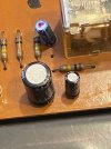
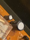
Can anyone tell me which is the Positive and Negative side of these 3 different Black Capacitors?

I am guessing it will say on the board after I remove the old Transistor but I don't want to take a chance. There are 2 on the first Yellow Board and 1 on the Darker Board.

I can not say without a doubt which side is - and which is +

Thank You
 

Attachments

  • 1318ec7d-c0a4-4525-b7b6-f536ff87be3e.jpg
    1318ec7d-c0a4-4525-b7b6-f536ff87be3e.jpg
    122.1 KB · Views: 21
  • 7af7e9ab-8526-411d-8412-ec277c247c2e.jpg
    7af7e9ab-8526-411d-8412-ec277c247c2e.jpg
    113.5 KB · Views: 22
  • e0907e45-7171-4df9-bada-15df598bb733.jpg
    e0907e45-7171-4df9-bada-15df598bb733.jpg
    111.1 KB · Views: 20
  • 323d5376-8c88-47ba-bd59-2b53b910ffab.jpg
    323d5376-8c88-47ba-bd59-2b53b910ffab.jpg
    87.4 KB · Views: 21
  • 0d1efd9d-9213-4f5b-9c0a-00ac251dc4ba.jpg
    0d1efd9d-9213-4f5b-9c0a-00ac251dc4ba.jpg
    104.7 KB · Views: 18
  • a11874ab-9951-4ac6-ac42-7ce050209842.jpg
    a11874ab-9951-4ac6-ac42-7ce050209842.jpg
    139.8 KB · Views: 27
C710 1uf/50V, sure you could use a film cap but unnecessary expense. Go with Nichicon UEP or similiar.
Likewise C711 100uf/6.3V, again go for UEP or,,, 100uf/16V or 25V

C609 on the power amp board 47uf/50V, there you can go for Nichicon UES or...
 
Not knowing this, I already placed my Mouser order on Sunday, so I am not going to make a 2nd small order. I will just leave these Bipolar caps in place and pray that they are still good and within tolerance.
 
Back
Top Bottom