• The move to the new server is done. There are some software and database maintenance updates in process. This has us passing the hat around to help out. We appreciate any donations. Seriously, even a dollar helps. The payment page may be found here - https://www.audiokarma.org/support.html

Yamaha CA-610 II Repair (and what's next)

MFRD

AK Subscriber
Subscriber
I got this nonworking CA-610 II from an AK member (thank you!).

I have a bit of a soft spot for Yamaha - the first motorcycle I rode at age 14 was a RD-250. First synth I ever played (tried to play that is) was a DX-7. My kids learned piano on a Yamaha upright grand. My AVR is a Yamaha. My bench receiver was a RX-830 that developed a bad channel. The RX-830 is a modest receiver, but it's leagues ahead of the plain-jane Onkyo that's filling in for it. I will definitely fix the RX-830.

In my experience, Yamaha products usually beat the competition within a given market segment. But I have no experience with their vintage hi-fi, so I was excited to have a chance to work on this late-70s 50wpc amplifier.
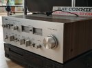
IMG_20260501_185029445_HDR.jpg

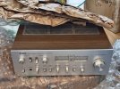
It doesn't hurt that the CA-610 II is, in my view at least, one of the best-looking amps of the period. Clean lines, minimalist design, all brushed aluminum and wood-grain, I think it looks more Scandinavian than Japanese. In some ways it is almost reminiscent of Dieter Rams' 1960's pioneering work for Braun, minus the architectural high concept of course.
IMG_20260422_154106184_HDR.jpg

Look at this face! How could anyone not be smitten? :)
 
Register to hide this ad
The other thing that was going to make this repair interesting for me was, I had resolved to start fixing stuff differently. I've been dabbling in this hobby for a couple of years now, and I'm far from good but I'm less hopeless than I used to be. I started out with the birdshot approach to repair (blanket-replace 50 or 70 parts at a time because the more parts you swap, the better the odds that one of them's bad), then I moved up to the automatic-rifle method (test lots of parts in circuit, pull out all the ones that don't test right, re-test them out of circuit, discover that they were totally fine to begin with; rinse and repeat until a bad part turns up - it will eventually!).

My goal was to progress to a more of a sniping method - don't touch any part until I know it's either the source of the problem, or part of it. Study service manual, block diagrams and schematics, take measurements until a credible theory develops regarding which part(s) are most likely at fault and why, then verify in situ and replace.

That's the route I told myself I was going to take from now on, and the CA-610 II would be my guinea pig.

Did I fix the amp? Yes. How many hours did I spend poring over service docs? Don't ask :) How many parts did I desolder? One.

IMG_20260603_135543898_HDR.jpg

So I'm pretty happy with how my new approach turned out for a first time.
 
That is absolutely the way it should be done- Congrats! Now what you have is an excellent amp that wasn't screwed up by the guy who worked on it before. Now give it a good burn-in to be sure all is sound, maybe give it a final test for good measure. Don't worry, a few more and you get very fast.
 
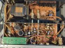
First thing first, I took the cover off to look around. No obvious horrors, pretty dusty / dirty but it looks fairly unmolested. The clear plastic wire jackets were really sticky, and the AC snubber cap cover was downright gooey. Not much corrosion, just a bit on the output transistor cases.

Normally my next go-to would have been to give everything a good clean, but in keeping with my new resolution I have to make it work first.

The presence of a relay next to the filter caps suggested some sort of protection circuitry.

IMG_20260603_135645849_HDR.jpg

So I powered it on my dim bulb tester. My smallest bulb was 100W which was probably too much, but at least it would mitigate disaster if there was a short. But it flashed for just a second and went dark. Good news.

However, no relay click. So I checked voltages at the output transistor legs, which all looked pretty normal so they were probably OK. Good sign.

IMG_20260530_100141395_HDR.jpg

I downloaded the service manual from the AK database. As often with Japanese gear, documentation is excellent, schematics are clear and well laid out and they include a ton of voltages; block diagrams, clear board layouts, exploded views, wiring diagram and parts lists both electrical and mechanical are all included. Which is good, because the PCBs themselves provide sparse information.

The only oddity is the naming convention used in the parts list - it does not match nor appears related in any way to the schematic. For instance, the NPN outputs (TR501 and TR502 in the schematic) are referenced thusly in the parts list

1780601709446.png

No reference to its TR501 schematic name. Weird.
 
Last edited:
  • Like
Reactions: mbz
Did I fix the amp? Yes. How many hours did I spend poring over service docs? Don't ask :) How many parts did I desolder? One.
And what did you learn? Guessing you can explain how the failed part produced the sysmtoms you saw, well done. Now compare with what you would have learned (=zip) by shotgun parts replacement. Because you have learned you are now better prepared for the next one...
 
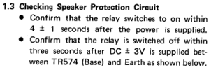
The service manual shows how to test the protection circuit

1780610742870.png
The corollary of the above is that if there were bad DC in the amp it would show up at the base of TR574 (guess that's positive DC, while negative would be at the base of TR575). But there were only millivolts, and voltages between TP1, 2, 3, and 4 and ground were all in the millivolts as well. I know some of these measurements are redundant since they all measure essentially the same thing, but one is never too careful :)

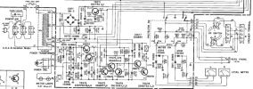
In any event, I figured it was safe to proceed on the assumption that the amp was working and that the protection circuit was not. Here it is:

1780611353901.png

Next I compared my voltages to the schematic's at TR574 thru TR578. All was good, except I had -34V instead of 730 mV at the collector of the TR577-8 Darlington pair. And sure enough I also had -34V at the relay coil, which looked like this (the waveform was continuous from L to R, not sure why the camera truncated it).

IMG_20260531_185256394_HDR.jpg
 

Attachments

  • 1780611255578.png
    1780611255578.png
    211.1 KB · Views: 3
  • Like
Reactions: mbz
None of that looked quite right, so back to the schematics. I will spare you my tedious and interminable deliberations, but at some point it started to emerge that in normal operation (no DC) TR574-6 would be off, while the TR577-8 pair would be on, allowing current to flow through the relay coil, and that the pair would be turned on by C584 when it charged above a certain voltage.

C584 charges through R584. which is fed from the TR572 collector. But, there is another trace that connects up to one of the 30VAC transformer secondaries through D579; however, D573 makes that a dead end, so to speak. The only junctions between D573 and D579 are C576 and R574, which decouple to ground.

R574 measured fine in circuit, so it was probably in good shape. As for C576:

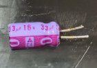
- Its in-circuit ESR was 3.3 ohms, which seems excessive even for a small 33uF 16V cap
- It was located right against the bridge rectifier - it's been slow-cooking for 50 years
- It's rated 16V, which seems low. It sits across a 30V secondary, minus whatever voltage is dropped across R574 (470 ohm), which I can't figure out how much current flows through it.

In any event, I thought there was enough evidence to allow actual removal of the component under my own new rules :)

And here it is, C576:

img2.jpg

img1.jpg

I replaced it with an old 47uF 16V I had lying around, for the time being. I powered up the amp... and heard the relay click! I connected speakers, a CD player, and I listened to Grace Jones for a while. No critical listening at this point, but it sounds pretty sweet and gets plenty loud! I'm pretty pleased how things have been turning out so far :)
 
There's more to do - the VU meters don't work, controls are scratchy, there may be an issue with the tone control switches between the bass and treble pots. And a good cleanup for sure.

Then, I want to make sure it's good to go for another 25 years; at the same time, I'm firmly in the less-is-more camp so I'll have to decide what kind of restoration is appropriate.

I hope my relating of my going through the motions wasn't too boring! If you have any tips towards improving either my process or the amp, please do share :)
 
I ran square waves through the Yamaha and watched the outputs on my scope. Turns out all tone controls work as expected and there is no issue with the tone switches. Lots of scratchiness though.

The VU meters appear functional (ie the needles move a little when the volume is up), but the meter board does not seem to output proper signals though it receives correct input. It looks like the board consists of some attenuating resistors selected by a switch and two half-bridge rectifiers.

In other news, the scope showed one channel with higher output than the other, and occasionally one channel shifts phase.

Cleaning all controls feels like a good next step
 
Folks, I assume the VU meters are not easily removable, is that correct? Best to leave them in place and be careful cleaning the front panel?

1000000358.jpg
 
Back
Top Bottom