MathiasNuyts
New Member
Hello everyone from Belgium, i'm new here and after reading allot of the threads i still can't get the protection relay to work on my Yamaha CA-610 amplifier.
So the problem lies somewhere around the relay. When i force the relay to close (i.e. with a clamp) the sound comes thru and the amp works perfectly, apart from the malfunctioning relay. So now i am trying to fix the problem.
No previous repairs where done.
And for story, this amplifier was used at a party when my dad was young (around 25 years ago) and they overheated (that's what he says) the amp by placing the record player on top when blasting it full volume. That is the last memory my dad has from this amplifier.
The first test i conducted was to check if the relay even works at all. A small 12V supply to the coil and voila, the relay closes. So i think this isn't the culprit.
Next i tested the idling current and adjusted it. Results:
TP1 and TP2 : -10,5mV (+ on TP1 and - on TP2)
TP3 and TP4: -10,8mV
TP2 to E: 28mV
TP4 to E: 14mV
Then i closed the relay with a clamp and tested the DC offset i think for the Lo and Ro
This gave a reading of 20,8mV. I think this is way too high as the service manual states 0V. I also think this is the problem as why the protection relay isn't closing but how can i fix this?
Then i tested the transistors around the relay.
TR429
19 / 33,2 / 18,5
TR428
18 / 31,9 / 15,5
TR427
0 / 0,4 / 0,4 (This is'n right i think)
TR426
1 / 0,4 / 0,4
I also tested the capacitors with a multimeter by checking for resistance at they all climbed in resistance value like i think they should.
Someone here with some information would be deeply appreciated
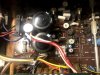

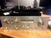
So the problem lies somewhere around the relay. When i force the relay to close (i.e. with a clamp) the sound comes thru and the amp works perfectly, apart from the malfunctioning relay. So now i am trying to fix the problem.
No previous repairs where done.
And for story, this amplifier was used at a party when my dad was young (around 25 years ago) and they overheated (that's what he says) the amp by placing the record player on top when blasting it full volume. That is the last memory my dad has from this amplifier.
The first test i conducted was to check if the relay even works at all. A small 12V supply to the coil and voila, the relay closes. So i think this isn't the culprit.
Next i tested the idling current and adjusted it. Results:
TP1 and TP2 : -10,5mV (+ on TP1 and - on TP2)
TP3 and TP4: -10,8mV
TP2 to E: 28mV
TP4 to E: 14mV
Then i closed the relay with a clamp and tested the DC offset i think for the Lo and Ro
This gave a reading of 20,8mV. I think this is way too high as the service manual states 0V. I also think this is the problem as why the protection relay isn't closing but how can i fix this?
Then i tested the transistors around the relay.
TR429
19 / 33,2 / 18,5
TR428
18 / 31,9 / 15,5
TR427
0 / 0,4 / 0,4 (This is'n right i think)
TR426
1 / 0,4 / 0,4
I also tested the capacitors with a multimeter by checking for resistance at they all climbed in resistance value like i think they should.
Someone here with some information would be deeply appreciated