• The move to the new server is done. There are some software and database maintenance updates in process. This has us passing the hat around to help out. We appreciate any donations. Seriously, even a dollar helps. The payment page may be found here - https://www.audiokarma.org/support.html

Yamaha CA-610ii Power light Only

Audi2014

Active Member
Good evening everyone,
Picked up a Yamaha CA-610ii for a project. Pulled off the cover and looked around the unit and found both fuses in tact.
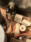
Looked closely at the 2 (50 volt) 470uf caps in the picture and they looked like the unit has been in a damp area. Only thing I get
when turning on the unit is the red power light. The unit smells musty. I will download the service manual. Any tips would be helpful.
Thanks
 

Attachments

  • f785be7a-d81c-4f50-a65d-802c996137ab.jpg
    f785be7a-d81c-4f50-a65d-802c996137ab.jpg
    90 KB · Views: 12
Register to hide this ad
Good evening everyone,
Picked up a Yamaha CA-610ii for a project. Pulled off the cover and looked around the unit and found both fuses in tact.
Looked closely at the 2 (50 volt) 470uf caps in the picture and they looked like the unit has been in a damp area. Only thing I get
when turning on the unit is the red power light. The unit smells musty. I will download the service manual. Any tips would be helpful.
Thanks
Start t-shooting the DC power supply.
 
Good morning,
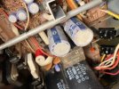
With meter and schematic in hand I went to test the voltages at the power supply area.Voltages were exactly what the schematic posted. I then tested one leg of the 250volt fuse and the relay kicked in and as soon as that happened the square white resistor on the left in the picture started glowing red and I shut everything down. I am guessing I am going to have to build a dim bulb tester to proceed my troubleshooting without damaging any components.
 

Attachments

  • IMG_2124.jpeg
    IMG_2124.jpeg
    261.7 KB · Views: 14
the square white resistor on the left in the picture started glowing red
R523 Left channel

Yes, DBT
Also test FR491(220) and test the emitter resistors,R523, R521 still in spec 0.47ohms.
Diode test left channel outputs TR501,3, c-e short?
Disconnect speakers, don't want to burn them
 
R523 Left channel

Yes, DBT
Also test FR491(220) and test the emitter resistors,R523, R521 still in spec 0.47ohms.
Diode test left channel outputs TR501,3, c-e short?
Disconnect speakers, don't want to burn them
Will do..thanks!
 
R523 Left channel

Yes, DBT
Also test FR491(220) and test the emitter resistors,R523, R521 still in spec 0.47ohms.
Diode test left channel outputs TR501,3, c-e short?
Disconnect speakers, don't want to burn them

R523 Left channel

Yes, DBT
Also test FR491(220) and test the emitter resistors,R523, R521 still in spec 0.47ohms.
Diode test left channel outputs TR501,3, c-e short?
Disconnect speakers, don't want to burn them
Good afternoon,
I finally have gotten some time to look at the Yamaha. I checked the 2 resistors R521,R523 and they are still good.Transistor Tr502.. reads 42 volts dc on both the emitter and collector. TR 501 is reading 6volts dc on the emitter and 26vdc on the collector. Haven’t checked resistor FR 421 just yet.
 
Good afternoon,
This is what I have found so far. I picked up a pair of output transistors for the left channel due to one tested as a short. When both are installed no relay click.
When I remove TR501and power up unit, the relay clicks . I am guessing that a component that is in its path has gone bad.
 
Last edited:
  • Like
Reactions: mbz
Results a little confusing
Transistor Tr502.. reads 42 volts dc on both the emitter and collector.
TR502 is on the right channel, suggests either it has failed short c-e or fault with driver TR498

When I remove TR501and power up unit, the relay clicks .
TR501 is for the left channel, removal will mask a problem from it or its driver TR497.

Suggest build a dim bulb tester to reduce damage to new parts.

I'd be tempted to pull both L&R output transistors and replace with diodes (1N4148, 1N400x, whatever you have handy), connect the diodes between output base and emitter solder tabs, for PNP outputs connect diode cathode to base, for NPN connect diode anode to base. The diodes replicate the b-e junction of the transistor. DBT power up and verify dc offset is ok
 
Proceeding methodically and documenting the results in the thread might be helpful if you want targeted help.

Pulling TR501 through 504 out of circuit and testing them might be a good way to start. No desoldering required.
 
Back
Top Bottom