Follow along with the video below to see how to install our site as a web app on your home screen.
Note: This feature may not be available in some browsers.
The move to the new server is done. There are some software and database maintenance updates in process. This has us passing the hat around to help out. We appreciate any donations. Seriously, even a dollar helps. The payment page may be found here - https://www.audiokarma.org/support.html
I think I really fixed the crackling and popping problem now having replaced those 3 transistors, tested from cold many times and in situations when I always had the disturbance, my guess is 2SC1061 was at fault as this one is getting scorching hot, also its soldering wasn't original.
Thank you everyone for tips, especially Avionic.
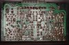
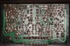
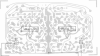
Meanwhile, this pcb is shown in Service manual as having 2 points TP one for each channel at which voltage is measured (between TP and the solder point in the middle of the bottom in the pic) and regulated with the 2 screws to be at 28V if I remember well. But how to find those 2 TP points. There's no pins for some reason like on other pcbs. The layout doesn't seem identical with the picture in manual. And should I really care abouting doing these settings?
Setting this must be really tricky as I think it requires tilting of the front?