SharkBait07
New Member
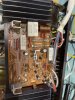
I am lost trying to figure out why this Yamaha CR-2020 will not come out of protection mode and can use some help and encouragement.
As a noob hobbyist, I have replaced recapped the unit and replaced the ecap and relay boards. The triac mode and Secant's FR riser board is all added. Some transistors on the ecap, output, and preamp daughter boards A and B have been replaced due to failure.
With everything back together both channels the unit was working although there was some screeching and popping coming out of the left output. For this I had disassembled and cleaned the pre-amp coupler switch but there was still popping and screeching on the left side. This happens with the coupler switch in both positions.
After removing and checking almost all the transistors hfe and continuity in the relay board (TR707 was installed backwards), and output boards the behavior changed. All fuses have been checked.
As it stands, the relay does not click to come out of protection when powering up the unit. I can get the unit to come out of protection only by removing the B+ fuse (FR601) on the right output board (with the brown wire).
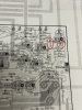
Here are the DC readings.
Relay Board Readings
AC (BE) 7.11
AC (BE) 7.11
TB (YE) 12.49
MB (OR) 12.51
E (BL) -0.005
-13 -10
LB (OR) 19.28
LB 19.29
LC 9.16
E -0.002
E -0.002
DL 7.46
PL 1.947
+25 (BR) 27.65
-25 (VI) -27.33
E (BL) 0
LL (WH) 0
R (RE) 0.004
E (BL) 0
B (BR) 24.21
r (VI) 0.009
I (GY) 0.009
HL (WH) 0
HR (RE) 0
SR (OR) 0
RI (YE) -0.004
E (BL) 0
LI (BR) 41.2
SL (BE) 0
Cap Board to Relay Board (L to R)
PIN 1 34.01 NB+
PIN 2 33.79 NB+
PIN 3 0 E
PIN 4 0 E
PIN 5 -34.64 NB-
PIN 6 -34.3 NB-
Cap Board
B+ 58
B- -58
Secant's Riser Board
R801 43.1 36.5
FR801 36.5 33.63
R802 -44.7 -38.4
FR802 -38.4 -34.36
Output Right
gy -109.5
wh -58.5
re 58.4
bl 0
br 41.1
rear trans. col. -58.3
front trans. col. 58.2
Output Left
gy -110
wh -58.5
re -58.5
bl 0
ye -0.005
rear trans. col. -58.3
front trans. col. 58.3
Any help is most appreciated.
As a noob hobbyist, I have replaced recapped the unit and replaced the ecap and relay boards. The triac mode and Secant's FR riser board is all added. Some transistors on the ecap, output, and preamp daughter boards A and B have been replaced due to failure.
With everything back together both channels the unit was working although there was some screeching and popping coming out of the left output. For this I had disassembled and cleaned the pre-amp coupler switch but there was still popping and screeching on the left side. This happens with the coupler switch in both positions.
After removing and checking almost all the transistors hfe and continuity in the relay board (TR707 was installed backwards), and output boards the behavior changed. All fuses have been checked.
As it stands, the relay does not click to come out of protection when powering up the unit. I can get the unit to come out of protection only by removing the B+ fuse (FR601) on the right output board (with the brown wire).
Here are the DC readings.
Relay Board Readings
AC (BE) 7.11
AC (BE) 7.11
TB (YE) 12.49
MB (OR) 12.51
E (BL) -0.005
-13 -10
LB (OR) 19.28
LB 19.29
LC 9.16
E -0.002
E -0.002
DL 7.46
PL 1.947
+25 (BR) 27.65
-25 (VI) -27.33
E (BL) 0
LL (WH) 0
R (RE) 0.004
E (BL) 0
B (BR) 24.21
r (VI) 0.009
I (GY) 0.009
HL (WH) 0
HR (RE) 0
SR (OR) 0
RI (YE) -0.004
E (BL) 0
LI (BR) 41.2
SL (BE) 0
Cap Board to Relay Board (L to R)
PIN 1 34.01 NB+
PIN 2 33.79 NB+
PIN 3 0 E
PIN 4 0 E
PIN 5 -34.64 NB-
PIN 6 -34.3 NB-
Cap Board
B+ 58
B- -58
Secant's Riser Board
R801 43.1 36.5
FR801 36.5 33.63
R802 -44.7 -38.4
FR802 -38.4 -34.36
Output Right
gy -109.5
wh -58.5
re 58.4
bl 0
br 41.1
rear trans. col. -58.3
front trans. col. 58.2
Output Left
gy -110
wh -58.5
re -58.5
bl 0
ye -0.005
rear trans. col. -58.3
front trans. col. 58.3
Any help is most appreciated.