

You are using an out of date browser. It may not display this or other websites correctly.
You should upgrade or use an alternative browser.
You should upgrade or use an alternative browser.
Yamaha CR-220 sound dies after a few seconds of sound - Please Help!

audiojung
Active Member
My voltage on J109 is funny. It starts from around 10V when I power on. Then it increases slowly to 27V over 10 seconds. When it goes over 25V, a little sound starts coming out with noise.
One strange thing on L1/L2/L3/L4 is that they are 42V/42V/42V/0V. 14V bulbs are connected there so this voltage is out of its spec.
One strange thing on L1/L2/L3/L4 is that they are 42V/42V/42V/0V. 14V bulbs are connected there so this voltage is out of its spec.
Last edited:
Finding that odd. Measuring Vdc, black probe connected to chassis/GND? Should blow the bulbs, are they working?One strange thing on L1/L2/L3/L4 is that they are 42V/42V/42V/0V. 14V bulbs are connected there so this voltage is out of its spec.
Is R802(?) 270ohw/2W series resistor in spec?
With both channels affected it's wise to check out the power supply 27Vdc for J109 is ok, though a little slow to get there.
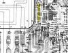
Check Voltage at J105, expect +25Vdc
Repeat for J104, expect -25Vdc

audiojung
Active Member
I went a little upstream and I found that TR801 has wrong voltage too.
TR801
E 27.2V ( Should be 30.9V )
B 27.8V ( Should be 31.4V )
C 41.8V ( correct )
TR803
C 22V ( Should be 41.5V )
Visually nothing is wrong but I wonder if I need to replace capacitors around TR801~803.
TR801
E 27.2V ( Should be 30.9V )
B 27.8V ( Should be 31.4V )
C 41.8V ( correct )
TR803
C 22V ( Should be 41.5V )
Visually nothing is wrong but I wonder if I need to replace capacitors around TR801~803.
Last edited:

Not a problem.One strange thing on L1/L2/L3/L4 is that they are 42V/42V/42V/0V.
Last edited:
Probably close enough -- not and issue..I went a little upstream and I found that TR801 has wrong voltage too.
TR801
E 27.2V ( Should be 30.9V )
B 27.8V ( Should be 31.4V )
C 41.8V ( correct )
Looks like either R808 (5w 390Ω) or C815 (47µf/50v) could be and issue. But not the root issue..TR803
C 22V ( Should be 41.5V )
This is a major issue..The voltage seems very wrong. I worried that some elements are burned out.
J104 -3V
J105 48V
audiojung
Active Member
R808 : I checked it when it is on the board and it is 380Ω. It seems good.
C815 : I took this out and it was 25µf instead of 47. I replaced it with a new one. Fortunately I had one.
However, it did not improve. C803 has still 22V on C.
I looked for TR719~722 but they don't show up in my manual. I assume that they are four on top of the circuit boards. I don't know which one is C but none of it has 23V. There are a couple of 46V so the input voltage must be wrong there too.
C815 : I took this out and it was 25µf instead of 47. I replaced it with a new one. Fortunately I had one.
However, it did not improve. C803 has still 22V on C.
I looked for TR719~722 but they don't show up in my manual. I assume that they are four on top of the circuit boards. I don't know which one is C but none of it has 23V. There are a couple of 46V so the input voltage must be wrong there too.
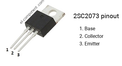
They would all four be fastened to a large heatsink. ( 2SA771 and 2SC1986 )I looked for TR719~722 but they don't show up in my manual.
Last edited:
Do you have your negative test probe connected to the metal chassis ? And are you probing with your red (pos) test probe ?There are a couple of 46V so the input voltage must be