akpasta
New Member
Hello,
I have an old Yamaha CR-400 receiver. Yesterday I was playing it really loud for a while and goofing around with a friend, talking about proper equalization, volume, etc. and I guess we must have been pushing it a little hard because it started emitting a funny smell, then the sound cut out, and it was slightly smoking. Opps.
I pulled the unit apart and found one of the three 250v/2a fuses blown. I replaced the fuse, turned the unit on, and the fuse blew again immediately. It would seem there is a short somewhere, and too much electricity is going to that fuse, and it is doing its job, hopefully preventing damage to my unit.
I am very inexperienced at diagnosing electronic problems. A friend told me to look for "burned or sooty" areas on the board, in an attempt to find a shorted/damaged electrical component and another friend recommended I find a schematic.
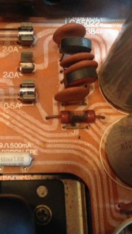
If you look to the bottom right of the third fuse, between it and one of the main Caps, the resistor below the smaller capacitors appears burned/sooty, but I cannot read what strength the resistor is, so I don't know how to properly test it. I tried to look it up on the schematic, but I can't read schematics well enough to do so :-(
This receiver functioned GREAT before this happened and was well taken care of. My father was the original owner, and it was passed on to me, so it hasn't changed hands, sat in thrift stores and been caked in dust, etc.
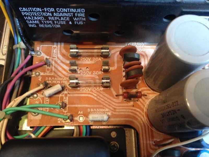
Here are two pictures of the general area, the fuse that keeps blowing has been removed, it is between the two that are pictured. In the second image you can see the resistor in question appears damaged. I located a schematic online (registration required) or I can send it to you in pdf format if you'd like to help me locate what this part may be called and it's resistor labeling so I can test it.
Thank you! Although I sorta know how to use the basic functions of a multimeter and can solder, I am really new at the theory and practice of electronics.
I have an old Yamaha CR-400 receiver. Yesterday I was playing it really loud for a while and goofing around with a friend, talking about proper equalization, volume, etc. and I guess we must have been pushing it a little hard because it started emitting a funny smell, then the sound cut out, and it was slightly smoking. Opps.
I pulled the unit apart and found one of the three 250v/2a fuses blown. I replaced the fuse, turned the unit on, and the fuse blew again immediately. It would seem there is a short somewhere, and too much electricity is going to that fuse, and it is doing its job, hopefully preventing damage to my unit.
I am very inexperienced at diagnosing electronic problems. A friend told me to look for "burned or sooty" areas on the board, in an attempt to find a shorted/damaged electrical component and another friend recommended I find a schematic.
If you look to the bottom right of the third fuse, between it and one of the main Caps, the resistor below the smaller capacitors appears burned/sooty, but I cannot read what strength the resistor is, so I don't know how to properly test it. I tried to look it up on the schematic, but I can't read schematics well enough to do so :-(
This receiver functioned GREAT before this happened and was well taken care of. My father was the original owner, and it was passed on to me, so it hasn't changed hands, sat in thrift stores and been caked in dust, etc.
Here are two pictures of the general area, the fuse that keeps blowing has been removed, it is between the two that are pictured. In the second image you can see the resistor in question appears damaged. I located a schematic online (registration required) or I can send it to you in pdf format if you'd like to help me locate what this part may be called and it's resistor labeling so I can test it.
Thank you! Although I sorta know how to use the basic functions of a multimeter and can solder, I am really new at the theory and practice of electronics.