• Please note that Audiokarma will be offline briefly for updates early on Monday morning, September 28th.

YAMAHA CR-420 Headphones Great! Speaker outs? Not so much...

JB8

Well-Known Member
Keep it pithy! I'll try!

Recently found unit in decent, yet very dirty shape. Pretty sure I'm the first person to poke around under the hood, started with cleaning, including DeoxIT, tightening chassis ground screws, exercising knobs, push buttons, polished the bright work as well - all of this before any significant testing.

Here's where I'm at:

1) Unit powers on great, relay kicks in as it should
2) Listening through headphone jack(s), FM sounds great, nice clean stereo separation, no issues
3) While listening through headphones, if I depress the speaker button I have the speakers attached to, the left channel sputters down to almost no sound, right channel remains in the fight, but both channels are distorted
4) With no headphones plugged in, only speakers, I get the same distortion, left channel fizzle when engaging the speaker pushbutton, right channel sounds horrendous

The typical troubleshooting I've read here is to clean the pots/switches, function switches as well, and then touch up some solder points. I'm happy to continue to work all of those angles, but thought I'd at least tap into the braintrust here to see if anyone has experienced this same scenario or has some suggestions on where to focus my attack!

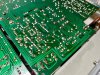
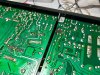
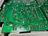
IMG_8809.jpg IMG_8806.jpg IMG_8808.jpg IMG_8807.jpg
 
Register to hide this ad
Try connecting/selecting speaker set B. Reads like a dirty speaker selector so try the other set/position.
Might be related to the difference between speaker impedance (8ohms) and headphones(maybe a few hundred ohms).
Start with spkr selector,

EDIT: Nah, your points 3)&4) indicates with the extra load from the speakers. The
switch is not the issue.

EDIT: Listening through headphones, select speaker set B (no speakers connected). Distortion?
Or disconnect spkr set A, listen through headphones then select set A. Hopefully this
will determine if a load issue.
 
Last edited:
Hey @mbz, thanks for jumping in!

The unit performs the same regardless of which speaker terminals I have the speakers attached to. If attached to the "B" terminals, when listening through headphones, I get the distortion when engaging the B speakers, but no noticeable change if I engage speakers A with no speakers attached. I tried it both ways, same results.

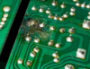
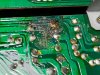
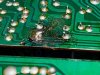
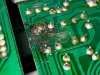
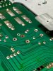
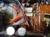
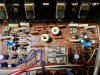
I figured someone would notice that section, here's a few pics plus one from topside. What do you think?

IMG_8811.jpg IMG_8812.jpg IMG_8813.jpg IMG_8814.jpg
 
Yeah, that solder joint on C513(?) does not look OEM. Been some stress in the area, copper traces still look ok, some
of the coating looks sick. Suggest clean up the area with some IPA(alcohol) board cleaner. You can use acetone but
be extremely careful to avoid plastic, only takes a few drops to seize switches. Redo that solder joint, ie, remove then resolder.

Possibly the extra load requirements for the speakers is dragging down the power supply, though C513 is for the regulated supply.
Consider replacing the caps in the area (psu). Nichicon UPW's? Might be a good time to do the main caps, Nichcon UKG are
popular however I like UKW's on the small amps though up the uf/Volts a little eg, 10000uf/50V.
 
  • Like
Reactions: JB8
Hey @mbz, I swapped out C513, no change, so I'm keen on getting after the psu caps and have started a list of caps I don't have in stock. I do have a question around upping uf/Volts - if I upgrade the main caps to the 10000uf/50V spec, do I need to upgrade most, all, or any of the other caps as well, or will just getting the main filter caps beefed up make enough of an impact?
 
Not every cap needs to be increased in voltage when increasing one to a higher voltage, and apart from main filter caps, the same capacitance value should be used as the original.

Its hard to tell which cap is going to bring about the biggest change in sound quality, or if any of them will. I've seen where replacing one bad cap really improves sound. On the other hand, I've recapped a whole integrated amp with only marginal improvement.
 
Last edited:
Thanks, @Semanon, totally hear you and appreciate the input. I'll likely just bump up the main filter caps and then just replace the rest of the psu caps with like values and see how it goes. Digikey order already placed, excited to get this thing fixed, and even if the caps aren't the issue I'll be giving it a new lease on life by swapping out all the old stuff (it's pretty cheap to do, and I enjoy the process).

I'll update soon, but if anyone else has experienced this same issue, please chime in! New caps or not, I need clear sound through both speaker outs!
 
  • Like
Reactions: mbz
Suggest also check emitter resistors (R443,4,5,6) are within spec, 0.47ohms + MM leed/probe resistance, so maybe 0.7ohms?
Also check R431,2,3,4 4.7 ohms on base of outputs. If both channels distorted then power supply would be the strong candidate.
 
  • Like
Reactions: JB8
UPDATE:

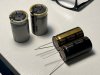
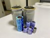
Replacement caps arrived, but when I was pulling the main filter caps I was introduced to Neutral pins... Had no idea this was a thing and struggled to pull the two caps because I didn't realize they had a third leg - totally my fault, should have examined the schematic with more detail but honestly, I would not have recognized the neutral leg even with more study.

At any rate, what should I do, will my new caps work and do I need to modify anything?

Also, even with using the Hakko sucker, one of the bases came loose, as seen in the pictures. Double whammy - weird caps and losing solder points... No worries, I'm sure both will be easy to address, with your assistance, please.

Couple pics to illustrate where I'm at:

IMG_8930.jpg IMG_8929.jpg
 
Third pin is for mechanical stability though track work shows that third pin is electrically connected(!).
The caps you have will work fine, connect banded/"negative" end as per originals
 
Thanks, @mbz, I appreciate the heads-up on the filter caps config, super helpful!

After replacing several caps on the power supply the distortion issue has persisted - no change except it's a more powerful, robust distortion due to the sweet new caps. :thumbsup:

I was missing a few values, so there are a couple of the old caps left, but I'll get them swapped out as well. Feels like the caps weren't the issue, which I'm fine with, so now back to the emitter resistors.

Can I get a bit more coaching on this process - power on or off, MM probe position (i.e. neg. on chassis ground, pos. probe on xyz) and MM on Ohms setting? And it was mentioned I should be seeing a value of .7 ohms, is that correct?

Lastly, for now, if the emitter resistors test out fine, any ideas on next steps? I know we've been focusing on the PS and I'm happy to keep replacing parts if necessary.

Thanks again!

IMG_8931.jpg IMG_8932.jpg IMG_8933.jpg
 
neg. on chassis ground, pos. probe on xyz) and MM on Ohms setting?
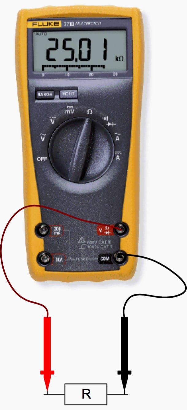
No..! Measure resistance across each component ( resistor).. Ideally you need to lift one lead to isolate the component from the circuit. Measure from one lead to the other lead with your MM in the Ω's function.


measuring-resistance-digital-multimeter.jpg
 
Last edited:
And it was mentioned I should be seeing a value of .7 ohms, is that correct?
No.. When measuring resistance values below 1 Ω. You have to subtract your test lead resistance from the measured value. Your test lead resistance is simply shorting the two probes together. Typical test lead resistance is .5 to .7 Ω..
 
  • Like
Reactions: JB8
Update:

All of the PS caps have been replaced, no change, still have static on left channel through speaker outs.

R443, 4, 5, 6 - all measured ~ .4 Ω while installed (POWER OFF), did not pull one leg to test (the solder points on this thing are so delicate I decided to leave them intact for a general resistance reading)

R431, 2, 3, 4 - all measured ~ 4.5-4.9 Ω

I'd also read a different thread on a similar issue someone was having with a CR-420, @mbz, you were on that thread as well. The person had some funky readings on TR413 and TR414, I saw some of the same discrepancies (did not capture the actual numbers, I will from now on as a reference), so I replaced both of those transistors as well with no change.

Now that I was on a "maybe it's a transistor issue" kick, I decided to freeze spray the transistors on the left channel of the MCB (1), no reaction, no change, nothing got worse or better.

Of course, I'm stumped, suggestions?
 
Go through the idle current adjustment procedure in the service manual and check/adjust the idle current if possible.
 
After letting the unit warm up, with MM in mV setting, I had no reading across TP-1 / TP-2, and at one point I had -6 Mv across TP-3 / TP-4, but then couldn't establish a meter reading after that, for either left or right side of amp. I don't have any clips, just probes, so I'm touching the probes to the test points as directed, with readings of 0.

DC output in mV at speaker terminals (A) are 130 on right, 85 at left. Both readings are when you first touch the speaker terminals, from inside the chassis, and then the values start to gradually drop once the probes are touching the terminals.
 
Back
Top Bottom