• The move to the new server is done. There are some software and database maintenance updates in process. This has us passing the hat around to help out. We appreciate any donations. Seriously, even a dollar helps. The payment page may be found here - https://www.audiokarma.org/support.html

Yamaha cr-420 intermittent distortion and bias drop. Output level triggered.

Cichoslav

Member
Hello guys, I need your assistance once again.

I bought a yamaha cr-420 for dirt cheap. Symptoms - distortion in left channel. I was surprised it worked flawlessly for like half an hour. Then it started to act up.

Well, this was't the only problem. Right channel bias couldn't be adjusted. I managed to fix it by replacing two bad transistors and it's all fine now.

Left channel although is a piece of work. I removed every single transistor and tested it out of circuit. Then I replaced every transistor except to-220 output transistors with substitutes, didn't help at all so I mounted originals back in place. I checked emitter resistors for continuity, they look fine. Removed and polished relay contacts just to make sure it's working correctly. Whole amp board seems to have original parts.

I used my scope&dmm to check what's going on with speaker terminal and bias. Link below.


This is seriously odd. I don't know where to start, as the problem is intermittent and it's triggered by rising volume level. (i checked amp input signal before coupling cap and it's a clean sine wave)
 
Register to hide this ad
Bias ----> idle current ---> quiescent current. Are all the same.. Once you start inputting a signal , the amplifier is no longer at rest ( idle ) . So your voltages across the emitter resistors will drastically change..

Have you gone through and cleaned all the switches and controls in the signal path ? Your symptom's suggest dirty switches..
 
Bias ----> idle current ---> quiescent current. Are all the same.. Once you start inputting a signal , the amplifier is no longer at rest ( idle ) . So your voltages across the emitter resistors will drastically change..

Have you gone through and cleaned all the switches and controls in the signal path ? Your symptom's suggest dirty switches..
Hello @avionic I was quietly hoping for you to respond. Well, I noticed that previous owner did that already. Visible solder work on selectors and speaker switches, clean selectors with no black oxidation.

I know that idle current changes with signal, but when this distortion is triggered, there's 1mV idle without signal and volume set to 0, impossible to readjust until powered up again.

I noticed some spilled electrolyte on c513 negative leg (if I compared it to the schematic correctly) and discoloration of the soldermask. I will scrape it off and make sure the copper layer is intact. Had similar issue with a-760ii, electrolyte ate copper. I suppose it's a longshot, but I have to check that anyway. Power supply board is completely recapped due to heat present close to cement resistors.

IMG_20240526_203659.jpg
IMG_20240526_203445.jpg
 
Acetone will make short work of those filthy solder side PCB.s.
 
Acetone will make short work of those filthy PCB.s.
That's what I usually use, but as you can see there's some residue looking like water spots after acetone dried. Any tips how to avoid that?

Also learned the hard way some time ago that value prints on elcaps tend to disappear after accidental acetone wipe with a brush
 
More than likely you have and output transistor playing badly under load. Check the output transistor solder connections.
 
Feed the unit a 1kHz sine wave, capture the distortion on the scope at the speaker terminals. Top or bottom half of sine wave distorted???
Repeat but check for ditortion at TR413b and then TR419base.
 
Both channels ?
Only in the bad one.
More than likely you have and output transistor playing badly under load. Check the output transistor solder connections.
Solder connections are fine, as I removed them, tested out of circuit and carefully put back in place.

There are 2sb595 and 2sd525. The only to-220 pairs I have in stock are mje15032g/33g and bd911/912. Which ones do you think will be better?

Have you replaced the idle current trimmers ?
Only deoxed and checked with ohmmeter, both seem to work correctly.

Thanks for the input, I'll get back to it after work. Replacing elements is easy. Replacing visibly damaged elements is even easier. But troubleshooting is something I can't do well.
 
Transistors replaced with bd911/bd912 from a reliable source. No magic smoke, hits like a train! But before I replaced them, I measured voltages on t401 and t407.

T401 c 24,4V e 25V
T401 c 16,6V e 16,9V when distortion triggered.

T407 c 24,4V e 25V
T407 c 10V e 17V when distortion triggered.

Now some stress tests and it should be fine. Or not. For now it plays very well with no distortion.

Big thanks to @avionic :)


Edit:

I checked the npn power transistor with my tester and forward voltage seemed to be a bit high, 0,78V. I gave it a shot and warmed it up with a lighter, then cooled it down with water. Turned out fV parameter was temperature dependent. The warmer, the lower the fV was. Looks like unit is fixed correctly. After 2 hours of blasting metal it got pretty hot due to undersized heatsink, bias is pretty stable, 18mV when cold, 17mV when hot.

IMG_20240527_204555.jpgIMG_20240527_204358.jpgIMG_20240527_203123.jpg
 
Last edited:
Nice looking black face...
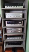
It is, but because of that black the dial and meter lights are... Pointless. Barely visible. However I noticed yamahas have bulletproof faces and markings. This is some seriously high quality IMO. Except cr-500 I own. This one has so delicate lettering it wears from even looking at it for too long. It's still in a waiting line, hoping to get it fixed and restored soon. I have six more devices to restore, and I suppose I'll be back for some help sooner than I can imagine. It's not a hobby anymore. It's a disease. Under my workbench there are 5 more.

IMG_20240523_205838.jpgIMG_20240521_175748.jpg
 
Back
Top Bottom