
• The move to the new server is done. There are some software and database maintenance updates in process. This has us passing the hat around to help out. We appreciate any donations. Seriously, even a dollar helps. The payment page may be found here - https://www.audiokarma.org/support.html

Yamaha CR-620 protection issue

dspear99ca

Super Member
I picked up this receiver a few years ago for next to nothing as it was sold as non-working. I recently re-discovered it while moving a few months ago and to investigate what is wrong with it.

The lights come on when I turn on the power switch, but there's no click from the protection relay. First thing I did was pull the outputs to see if that would help - couple of screws an no de-soldering - but alas, no change.

I checked voltages at the emitters of each driver transistor (total of 4 in both channels) and while it took awhile to stablize after power-up, they generally ended up somewhere between -1V and +1V, "in the zone", shouldn't be enough to trip the protection.

I checked the collector of TR809 which powers the relay, schematic notes it should be "0" and that's what I read. So... not sure what's going on. If there's no power to the relay (0V) then it ain't gonna' click. The schematic doesn't show the internal wiring of the relay, it just shows a rectangle with a connection to the collector of TR809, another connection to ground, and a diode around the relay from TR809 to ground. A dashed line indicates that the relay controls the connection from output stage to speakers. I've attached a photo of the protection circuit. Anybody have ideas as to what I should check next, or how this relay is supposed to close with 0V applied to it per the schematic?CR620 Protection.JPG
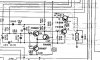
 
Last edited:
Register to hide this ad
I believe those may be backward per the schematic. The base shows 21.4V and emitter shows 21.9V. As soon as the base is about 0.6V lower than the emitter, the voltage (about 20V) would be applied to the relay operating coil. Once current flows, the dropping resistor (R820) would reduce that voltage to around 12-14V.
 
Yes... sorry I was looking at a paper copy of the schematic when I measured and made notes - everything is very small... the Emitter anticipated value should be 21.9V and the base 21.4V from the schematic. I am quite sure I measured the actual voltages correctly - but of course I will re-check them tonight...

E=21.3V (should be 21.9V)
B=22.1V (should be 21.4V)

The base voltage is higher than the emitter by 0.8V so the transistor is turned off - hence the 0V at the collector. If the circuit had the voltage values indicated in the schematic you'd need only 0.1-0.2V drop at the base for the transistor to turn on (E-B voltage differential >0.6V). Is it normal to have a circuit designed in this way, so that a very tiny fluctuation in voltage (0.1V or 0.5% which increases V(be) from 0.5 to 0.6V) trips the protection circuit? The way it is now there would have to be 1.4-1.5V (0.8V drop at the base plus 0.6V forward bias)... is this correct?

I don't really understand how this circuit works, per my original post how can the relay close with the voltages shown if it is powered by TR809? Is it possible that the relay DISconnects the outputs when it is activated rather than the reverse?
 
Have you checked that diode? Might also try a light tap. are you getting voltage to the actual relay terminals?
 
It is possible that the relay would be using the NC contacts instead of the NO contacts, but that would not provide a very reliable failsafe for power-up and power-down situations. Further, the schematic shows the contacts as NO.

In order for the relay to energize, and for the speaker contacts to close, the base would have to be forward biased, or about 0.6V more negative than the emitter. If that were the case (for the indicated PNP device) the collector voltage should be about the same as the 22V emitter source. As above, once the transistor has switched on and current flows, the collector would drop to about 13V due to R820. The protection circuit is very sensitive, and differential voltages are necessarily small. TR808 will also have to turn on for the relay to operate.
 
E = 21.3V (should be 21.4V)
B = 22.1V (should be 21.9V)
If the collector has less than 12 v. Replace TR809. Look at the Relay coil and the flyback diode.(D811) as well. I've never seen a bad flyback diode.But I guess anything is possible.
 
Last edited:
Thank you for the reply. I am on a mission to understand how this works, I apologize for the questions as the issue probably seems very simple to you.

What you said about the operation of the protection circuit makes sense. But... the schematic shows 0V at the collector of TR809 which powers the relay, not 22V or 13V. How does the relay coil get power? In order to read 0V between the collector and ground, at least one of these must be true:

1. diode D811 is shorted to ground
2. relay coil has zero (unmeasurable) resistance hence no measurable voltage drop
3. TR809 is not turned on so there's no power at the collector and there's no current flowing

My gut says TR809 would get pretty warm if #1 or #2 were true but maybe the circuit is designed to withstand a dead short in this location, I have wondered at the cascading transistors but that would help.

Hmmmm....

I will check the diode and give the relay a tap when I get home.
 
The collector has less than 12V... it has 0V. I double-checked the B/E voltages, it's a 2SD544 transistor so looking at the flat side the base is on the left. Yes?

For a PNP to turn on, the base has to be lower potential than the emitter, right? My base is more positive than the emitter.
 
What voltages are you seeing around TR808?
the schematic shows 0V at the collector of TR809 which powers the relay, not 22V or 13V.
The schematic is drawn depicting the protect circuit activated with the amplifier outputs shorted to ground.Thats why the collector has zero volts in the schematic.Because the relay is de-energized when in protect mode so the relays normally closed (NC) contacts are grounded??? WTF
 
Last edited:
Huh. OK. Odd to show it in nonfunctional form in the schematic but that makes sense. So I'll move on to TR808 as the voltage at the base of TR809 is too high. Thank you very much, I really appreciate the help.
 
Odd to show it in nonfunctional form in the schematic
@avionic has the ball.
----------------
just to explain all sm or schematics showing the voltages are amps or receivers etc in 'idle mode'... no inputs outputs connected, vol. off, tone controls in neutral positions. note any ser. man. might state aux. switch selected or any other sm directions.

back to my fav yammi guy.
 
.Because the relay is de-energized when in protect mode so the relays normally closed (NC) contacts are grounded.
Actually the relay contact wiring is depicted incorrectly on the schematic. The common contact should be connected to the speakers/headphone. The NC contacts to ground and NO contacts to the amplifier output.
 
LOL .. Shorting amplifier output to ground when in protect mode is a big no no.:yikes:
 
I couldn't find a pinout for TR808 - 2SC1918. So I traced the circuit visually, and found out a couple of things. First off, the Sanyo datasheet I was using for 2SB544 didn't match what I was seeing on the PCB. Looking at the flat face of both TR808 & 809, the pinout appears to be the same E-C-B from left to right. I measured:

TR809:

Right leg (B) = 21.1
Middle leg (C) = 0
Left leg (E) = 22.0

TR808:

Right leg (B) = 0.2
Middle leg (C) = 20.9
Left leg (e) = 0

If the schematic shows the voltages when the protection circuit is activated, everything matches with what I am seeing. What do I check next?
 
when the protection circuit is activated
Amp is in idle mode and relay is NOT activated. protection circuits while running a load activate if something is gone wrong however avionic is trying find out if the actual circuitry is faulty and engaged or something up stream.
--------------------
Sorry avionic just wanted to clear that up.. Man this is getting good!. :lurk: like reading a Master at work.
good schema would clear things up for OP.
 
...If the schematic shows the voltages when the protection circuit is activated, everything matches with what I am seeing.

That is the problem. I believe the schematic does NOT show the circuit with the protection relay closed (energized). Clearly, the relay contacts are drawn N.O., clearly, the relay coil is sourced (not sunk) by the switching transistor TR809 because the opposite end of the coil is directly grounded, and clearly, the schematic indicates 0V at the relay coil, which would make it de-energized.

As was mentioned previously, that seems unusual, but in my limited experience, Yamaha is a little like Siemens in that regard, and they tend to do some unusual things and follow some strange/non-standard conventions.
 
Back
Top Bottom