If this is the same voltage at the output of each amplifier. Then yes, that would be a good indication.DC seems well and good at 14mv


If this is the same voltage at the output of each amplifier. Then yes, that would be a good indication.DC seems well and good at 14mv
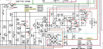
The schematic is showing the circuit " in protection" mode voltages. Look at the relay contacts positioning in the schematic.Tested all voltages in the protect circuit, everything seems to be very close to what the schematic is showing.

Yup, that’s what I read from the previous posts. I did make notes of the voltages. I will post here when I got back home.The schematic is showing the circuit " in protection" mode voltages.
Reflowed both transistors and the relay, issue is still there.Check/reflow solder connections on TR809. Ideally you need around 24v on the collector of TR809 to energize the relay. But in this case, it will be closer to 20v.
Very carefully measure the DC voltage on the 4 relay contacts. Should be close to zero volts or a few millivolts.Main amp may have different voltages, maybe

Very carefully measure the DC voltage on the 4 relay contacts. Should be close to zero volts or a few millivolts.
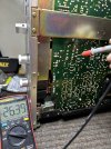
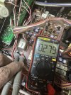
Not really sure if this is the diode. It’s just beside the relay. In circuit, forward and reverse diode test 0.279volts. Out of circuit as I desolder this this morning to test it checks out. Forward bias around 0.5v, reverse is high resistance.has the flyback diode been checked yet ?
yes that's it .it appears fineNot really sure if this is the diode. It’s just beside the relay. In circuit, forward and reverse diode test 0.279volts. Out of circuit as I desolder this this morning to test it checks out. Forward bias around 0.5v, reverse is high resistance.
Yes, both channels and at both transistors.is that same both channels ?
looking like a power supply issue thenYes, both channels and at both transistors.
I’m out for now for visit. Will check the power supply section when I get back.looking like a power supply issue then
I’m out for now for visit. Will check the power supply section when I get back.
Pretty sure the two main caps gives the right voltages 39v and -39v. Those were the voltages I checked first and double check again.
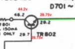
Per the attached schematic on my response to avionic up top. Red caption are my actual readings.check tr802 voltages first