• The move to the new server is done. There are some software and database maintenance updates in process. This has us passing the hat around to help out. We appreciate any donations. Seriously, even a dollar helps. The payment page may be found here - https://www.audiokarma.org/support.html

Yamaha cr-820 relay not clicking, where to start troubleshooting?

Snow_

New Member
Hello folks,

my yamaha cr-820 had shorted output transistors on the left channel, due to a broken piece of plastic allowing a short to the heatsink.
I fixed that by replacing both of the left channel transistors and now the 68ohm fusible resistor doesnt burn up on me anymore.
But neither does the relay click nor do I get any voltage on the idle current measuring points for the left channel (right one is fine).
I also think tr720-721-722 seem to get hotter than ususal, but they test fine.
Where do I keep searching for a fault, caused by the short?
I´ve been pulling transistors with no plan, just to check them, but its a lot of work and I cant find anything wrong.
Has anyone here run into the same problem beforehand and could help me out?
I am completly self tought, which means my experience in troubleshooting is limited, but I know how to solder, meassure and replace.
I aprecciate any help!

Konrad a.k.a. Snow
 
Register to hide this ad
You can test the transistors without pulling them but the readings don't always make sense. Since you have a good, working channel, comparing left and right channel readings should give you good feedback on whether or not the part being tested is OK.

There are several fusible resistors in Yamaha amps and receivers and they don't always burn when they fail. Look for 'FRxxx' parts on the schematic and find them on the boards. I would recommend that you measure all of the fusible resistors, also in circuit, comparing right and left channels to see if anything jumps out at you.

Good luck.
 
broken piece of plastic allowing a short to the heatsink.
Mica not plastic. :thumbsup:
I also think tr720-721-722 seem to get hotter than ususal, but they test fine.
TR720 and 722 are on the right, working, channel. TR721 is in the left channel. Look at TR719 and 721. Measure the (ECB) DC voltages around these two and post your results.

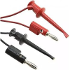
Connect your black multimeter test lead to one of the black speaker binding posts. With the red multimeter test probe. Measure each of the transistors ECB leads. Highly recommend that you use mini- grabbers to avoid shorting out transistors. With slips of the test probe. :thumbsup: Similar to these.
1727546568357.png
 
Last edited:
You can test the transistors without pulling them but the readings don't always make sense. Since you have a good, working channel, comparing left and right channel readings should give you good feedback on whether or not the part being tested is OK.

There are several fusible resistors in Yamaha amps and receivers and they don't always burn when they fail. Look for 'FRxxx' parts on the schematic and find them on the boards. I would recommend that you measure all of the fusible resistors, also in circuit, comparing right and left channels to see if anything jumps out at you.

Good luck.
Yeah you are right, thank you.
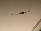
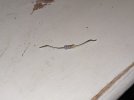
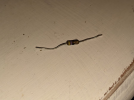
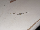
I found two burned resitstors hidden under a heat shield, right next to the 68ohm fusible resistor. The thing is, Im not sure what their values are supposed to be. Maybe you or @avionic can help me out with that.
The Resistor with 4 stripes is the one on the left, the one with 5 strips on the right, both are labelled with a 47 on the schematic.
I tried some resistors identification apps, but the values dont seem right to me.
Oh and the 4 striped one shows around 7 ohms, while the 5 striped one shows nothing.
Really would appreciate some help on how to figure the value out, the service manuals for the yamaha cr 820 leave much to be desired...

Btw, relay clicks again, got delivered a broken output transitor with no voltage drop off on the emitter, replacing that got me out off protection mode, but the left channel is still dead, due to these resistors probably.
 

Attachments

  • IMG-20241014-WA0001.jpg
    IMG-20241014-WA0001.jpg
    134.5 KB · Views: 16
  • IMG-20241014-WA0002.jpg
    IMG-20241014-WA0002.jpg
    148.4 KB · Views: 17
  • IMG-20241014-WA0003.jpg
    IMG-20241014-WA0003.jpg
    58.6 KB · Views: 16
  • IMG-20241014-WA0004.jpg
    IMG-20241014-WA0004.jpg
    69.7 KB · Views: 16
The same as the first one 4.7Ω 5% 1/4 watt -- disreguard the 5th violet band.
1728922214635.png


why was the 5 band there?
5th band
The temperature coefficient band of a resistor is the fifth band on a resistor that indicates the temperature coefficient. The temperature coefficient of resistance (TCR) is the relative change in resistance per degree of temperature change.

Not a critical parameter for this app.
 
Resistors usually always go higher resistance before burning open.

Burning open = infinite resistance :biggrin:
 
Mica not plastic. :thumbsup:

TR720 and 722 are on the right, working, channel. TR721 is in the left channel. Look at TR719 and 721. Measure the (ECB) DC voltages around these two and post your results.

Connect your black multimeter test lead to one of the black speaker binding posts. With the red multimeter test probe. Measure each of the transistors ECB leads. Highly recommend that you use mini- grabbers to avoid shorting out transistors. With slips of the test probe. :thumbsup: Similar to these.
View attachment 3307743
I kid you not, it wasnt the mica pad, the screw goes through the heatsink and is isolated by a plastic piece, which was broken in half
 
Last edited:
That 68Ω/85ma resistor is a fusible resistor.. Which calculates to a 1/2 watt resistor . The replacement that is in there looks to be a 2- or 3-watt MOX resistor. Which is way too large for a fusible. Like replacing a 1/2A fuse with a 2A or 3A fuse... :yikes:

MOX --> metal oxide

Better add this to your shopping list..

Yeah replacing that one is already planned, it just was the only 68ohm resistor I had available. Pretty sure it's a 2W carbon resistor
 
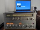
Up and running again, all caps replaced, most transistors replaced, now only the wood casing has to be done.
Maybe I'll be able to borrow a oscilloscope for further testing.
Thanks for the help.
 

Attachments

  • PXL_20241018_122334130.jpg
    PXL_20241018_122334130.jpg
    73.8 KB · Views: 10
Back
Top Bottom