• The move to the new server is done. There are some software and database maintenance updates in process. This has us passing the hat around to help out. We appreciate any donations. Seriously, even a dollar helps. The payment page may be found here - https://www.audiokarma.org/support.html

Yamaha HTR 5650 - Power on Immediate Power Off

Thinking you would be wrong in your assumption.

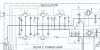
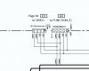
From the service manual, shows +/-5,12V regulators
View attachment 2453502


Exactly what was the diagnostic message, ie PS PRT nnn
A voltage of 94-95% unlikely to be regulator failure, more likely to be a leaky cap, maybe post a pic of that board highlighted above, showing caps. I'd be surprised if 95% voltage would trigger protection, considering mains AC drift.
I've taken the entire unit apart (aside from the detaching the heatsink) as I wanted to look the boards over under a magnifying lens for broken or loose solder joints. Which I found none. Then I had a look around at all the capacitors (as I have worked on many TV's stereos computer motherboards that have had bad caps) so I know how easily it can be for a cap to be out of spec and cause the device to not work or power on/off etc. However after close inspection I can't see any caps looking bad in any way no budging no leaking and none are loose soldered. But now that I know the location to look - I will be going over this area much closer when I do tests. Also when I go into diagnostics which buttons do I need to press to get to the screen you are asking about?
 
Thinking you would be wrong in your assumption.

From the service manual, shows +/-5,12V regulators
View attachment 2453502


Exactly what was the diagnostic message, ie PS PRT nnn
A voltage of 94-95% unlikely to be regulator failure, more likely to be a leaky cap, maybe post a pic of that board highlighted above, showing caps. I'd be surprised if 95% voltage would trigger protection, considering mains AC drift.
It says PS PRT 0% D (does this help narrow it down before I take it apart)
 
It says PS PRT 0% D (does this help narrow it down before I take it apart)
One or more of the voltage regulators is down, outputting 0Vdc, should be easy to detect with board in situ, so I wouldn't take it a part yet. All 5 regulator outputs need to be checked however I'd be starting with culprits from "Jube marsh
3 of 5 were shorted
2 x 78m05
1 x 78m12"
upload_2022-1-16_19-24-38.png
 
One or more of the voltage regulators is down, outputting 0Vdc, should be easy to detect with board in situ, so I wouldn't take it a part yet. All 5 regulator outputs need to be checked however I'd be starting with culprits from "Jube marsh
3 of 5 were shorted
2 x 78m05
1 x 78m12"
View attachment 2454349
I am assuming the #'s in red are the intended voltages at those locations?
Will the unit give full power to these in diagnostic mode? (assuming they were working and I entered diagnostic mode)

UPDATE: I've tested them only the one 79m12 on the outside is producing anything near spec. On the one side it's reading around +20.1v the second time I powered it on to test it read 19.6v (I mean these sound about right according to the schematic you included other than the reverse polarity) the other side is 7.6v or so... which is out of spec.... all the others are either outputting nothing or a slight voltage is present. I assume then they are all bad other than the one. So I will just replace all 5. Thanks again for all your inputs/efforts! (I will update you once the parts arrive)
One last question if you don't mind??
I see similar part #'s of these but no exact matches - for example there is 79m12-BT 79m12-BTC 79m12-CT 79m12-ND etc but no A's as in 79m12-A Looking at the data sheets it seems most of these differences boils down to operating temperatures and PSRR (Power Supply Rejection Ratio) do you think any of these matter much in this application? I'm figuring any of these should more or less work so long as it's the same form factor.
 
Last edited:
  • Like
Reactions: mbz
I haven't checked the datasheet (you should do this) but would be looking at the MC7805, MC7812 and MC79xx series. Probably some lower noise types about but for a HTR expect the above to be ok.
 
I haven't checked the datasheet (you should do this) but would be looking at the MC7805, MC7812 and MC79xx series. Probably some lower noise types about but for a HTR expect the above to be ok.
Just an update - I replaced all of the regulators - with as close as I could find matches - DigiKey did not have any "m" series like the 79m12 and 79m05 - so i went with the 7912 and 7905 - put it al back together and when attempting to power the unit would on it would click as if it was going to come on but then not come on - I noticed a small puff of smoke that smelt like heat burning dust coming from near the regulators but not the regulators themselves - upon close inspection nothing seemed burnt or blown - so I made a new order from Mouser with the better matched "m" series regulators - after replacing all of them with all new regulators - the same issue happened - I saw smoke that again smelt like heat/dust burning - however I tried to power it on again - and it actually turned on and stayed on - then I saw the source of the dust smoke which was coming from resistor at R414 which I watched get so hot that it turned red (I quickly unplugged unit) - I have been over and over this unit and see no shorts and nothing seems blown. (I might add that I did not replace the LM61CIZ thermal sensor)
Any idea what might be causing this???
 
Last edited:
R414 which I watched get so hot that it turned red (
R414 is between the rectifier and regulator(-5V) input, probably also takes out the regulator. Post a pic of the area/half board showing caps
etc... Maybe a cap has failed(C414, C408??). With unit powered off measure resistance from R414(either side) to amp chassis. Repeat for other side of R414.

-5V supply feeds some IC's on the video and function boards
Work back from here
upload_2022-2-3_7-20-3.png


Remember to replace R414
 
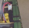
Here are a number of photos of the area - you can see right near the regulators is a red/grey wire going off the board - which I took a photo of where it goes - which is to the composite video daughter board and it has +12v printed on the daughter board so it's routing the 12v there from factory.
 

Attachments

  • caps & resist 414 overhead.jpg
    caps & resist 414 overhead.jpg
    60.2 KB · Views: 26
  • caps & resist overhead.jpg
    caps & resist overhead.jpg
    66.8 KB · Views: 24
  • caps & resist top view.jpg
    caps & resist top view.jpg
    87.9 KB · Views: 24
  • caps & resist top view2.jpg
    caps & resist top view2.jpg
    80.8 KB · Views: 24
  • caps & resist.jpg
    caps & resist.jpg
    74.4 KB · Views: 22
  • DSCF1349.JPG
    DSCF1349.JPG
    70.7 KB · Views: 25
  • 12v.jpg
    12v.jpg
    88.8 KB · Views: 26
  • Like
Reactions: mbz
Thanks for pix, caps "look" fine, no venting, no shrunken sleeves... Following on from R414 smoking, appears to be on the -5V supply, tempted to take the load off the -5V supply and see if power supply normalises/R414 still gets warm, can you find the other end of W607 on the video card, is it possible to unplug or appears to be wire only.
 
Thanks for pix, caps "look" fine, no venting, no shrunken sleeves... Following on from R414 smoking, appears to be on the -5V supply, tempted to take the load off the -5V supply and see if power supply normalises/R414 still gets warm, can you find the other end of W607 on the video card, is it possible to unplug or appears to be wire only.
Hmmm.... there is no W607 there are two wires I think W404 and W403 which is what the red/grey wire attaches to then goes to the video daughter board. There are other wires on other boards but they are labeled W1xx I see no W6xx's anywhere. Also looking at the more recent schematic you posted - it also seems off? it shows 5volts headed to the video daughter board but on the video daughter board I see all the wires labeled as +12volts... perhaps you are looking at the wrong model? I just realized the original post was for a 5650 - however I began commenting about the 5640. (since Jube Marsh said he had both the 5650 and 5640 with the same problem)

Anyhow I assume you meant the other end of the red/grey wire in the photo that goes to the main board with the voltage regulators in the other photos I sent - it does not detach. Just for fun I removed the video board and attempted to power on - still the same result (mind you now that R414 has gotten so hot so many times - it may have finally failed - which could be the cause of it not turning on now...)

I have included a photo of the video daughter board inputs these are the only connectors there are and as you can see they all are using 12Volts not 5.
 

Attachments

  • DSCF1365.JPG
    DSCF1365.JPG
    50.1 KB · Views: 17
upload_2022-2-3_13-55-18.png

Just for fun I removed the video board and attempted to power on - still the same result (mind you now that R414 has gotten so hot so many times - it may have finally failed - which could be the cause of it not turning on now...)
Best to replace R414 and repeat test, does R414 get warm, maybe the CPU is waiting for a reset_ack from the video board before proceeding with power up? Problem appears to be -5V supply. Did you check resistance from R414 to chassis?
 
hi guys,

I picked up a htr-5640 from C.L. today. This post seems to be the closest to describing so called problem I'm having.

Can anyone tell/explain the difference between the D and the E from pics below? My issue is with the E.
 

Attachments

  • HTR-5640 Screenshot 2022-09-17 233335.png
    HTR-5640 Screenshot 2022-09-17 233335.png
    386.2 KB · Views: 20
  • HTR-5640 Screenshot_20220917-233438_Gallery.jpg
    HTR-5640 Screenshot_20220917-233438_Gallery.jpg
    51.5 KB · Views: 20
Last edited:
Can anyone tell/explain the difference between the D and the E from pics below? My issue is with the E.

Vaguely recall that the D/E correspond to a firmware version (or similiar). Key info is the PS PRT 25%.
Fault in regulated power supply, maybe 1-2hours work for an experianced tech with all the tools/parts.
I'd start by checking the voltage regulators then caps etc as per this thread.
 
Vaguely recall that the D/E correspond to a firmware version (or similiar). Key info is the PS PRT 25%.
Fault in regulated power supply, maybe 1-2hours work for an experianced tech with all the tools/parts.
I'd start by checking the voltage regulators then caps etc as per this thread.


Ok cool, thank you.

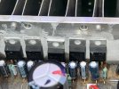
I went through and and checked voltages on the IC regulators and only one was faulty (far left from pic below) wasnt getting its 5 volts. Replaced and it works. Man I am amazed at how this system sounds. Added a cheap ebay bluetooth reciever and I'm lovin it.

Thank you to all in the group that posted, this helps a lot of people who may not even post.
 

Attachments

  • 20220918_011738.jpg
    20220918_011738.jpg
    109.6 KB · Views: 27
Resurrection of a year old thread. Having exactly the same issue with ps prt 20% F on a 5660. I suspect it’s one or more voltage regulators that are located on the heatsink. I’d really like to go over the service manual before taking it apart but all the google links I can find don’t work. Does anyone have the manual or know where a link still works.
 
Link at hifiengine works ok, reasonable scan. Need to register with hifiengine, it's safe, no spam etc, widely used in diy, just about the first choice for manuals. Some sites have exceptional quality scans but the cost a few bucks...

Yeah that seems the best link but when I try and register the site says they are no longer accepting new accounts. Can someone with an account download it for me?
 
Hey everyone, bringing back and old thread here. I was having the the power supply cutoff issue and it was showing 25%. I replaced the voltage regulators and when I turned it on it clicked and a little burst of smoke shot out. Did I use the wrong replacements?

From left to right
7805ACT
7805ACT
79M05C
7812ACT
79M12BT
IMG_3090.jpeg
 
Back
Top Bottom