


amr2
Well-Known Member
From Audio power amplifier design. Douglas Self, Sixth Edition
To whom it may concern...
Yamaha non-switching
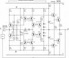
Yamaha did not want to be left out of the non-switching business. Their version was called Hyperbolic Conversion Amplification (HCA). The implication seems to be that two hyperbolic curves can be combined to give a straight line; this is not true mathematically as far as I am aware, though certainly two parabolas (square law curves) can be combined to result in a straight line. The relevant patent appears to be 4,803,441 by Noro,47 which references an earlier patent by Yamaguchi, 48 and confirms that HCA is based on square law characteristics. More hyperbole than hyperbolic, I feel. HCA was applied to the Yamaha MX-1000 amplifier in 1989; it was also applied to the MX-2000 (1988) though the details of the circuitry are rather different. A simplified version of the MX-1000 application is shown in Figure 4.22. A and B are sub-rails which are driven up and down with the output by C2 and C3. Biasing diodes D1, D2 set up a constant current in the current-mirror Q9, Q7, while D3, D4 do the same for current-mirror Q10, Q8. The signal is applied through the voltage amplifier, which has a low output impedance, and is converted from voltage to current by R15, which sees a low impedance at the emitters of Q7 and Q8. The output current from mirror Q9, Q7 is bounced off the upper sub-rail A by mirror Q5. Q3, and likewise the output of mirror Q10, Q8 is bounced off the lower sub-rail B by mirror Q6, Q4. The output current from Q3 is fed to amplifier Q1, which is also fed with a version of the output signal, and Q1 controls driver Q11. Likewise for the lower half of the circuit. The output stage itself is a conventional Type II emitterfollower configuration. The fundamental principle is that the product (not the sum) of the output currents from Q7 and Q8 is constant. Therefore, no matter how hard the circuit is driven, the smaller current never reaches zero, and therefore the output devices never turn off.
Some of the Yamaha amplifiers with discrete HCA circuitry were the MX-630, MX-800, and MX 1000. The MX-1000 (260 W/8U) also had what Yamaha called Advanced Power Supply Circuitry (APS), which as far as I can tell from the schematic was a form of Class-G. Later the HCA circuitry was incorporated in an IC called the BA3122 N, being applied to the MX-1 and MX-2 in 1993. The service manuals for these amplifiers give the internal circuit of the IC, revealing that it has four linked current-mirrors as shown in Figure 4.22, but offer no component values. The Yamaha AX-730, AX-930, AX-1050, and AX-1070 used the BA3122 N HCA IC and it is believed it was used in the AX-1090, but this is not so far confirmed.
Non-switching Conclusions
The fact that that non-switching technology quietly faded away after a few years, despite what was clearly a major effort by several manufacturers, seems to indicate that it was not satisfactory in practice. It is notable that in all the promotional literature, emphasis is laid on how it prevents switching distortion, i.e., that caused at HF by output devices turning off slowly, rather than on how crossover distortion in general is reduced. For the latter to be true, the nonswitching action would have to make the two halves of Class-B conduction splice together in a better way than occurs with a fixed bias voltage, and I have yet to see any evidence that was achieved.
To whom it may concern...
Yamaha non-switching
Yamaha did not want to be left out of the non-switching business. Their version was called Hyperbolic Conversion Amplification (HCA). The implication seems to be that two hyperbolic curves can be combined to give a straight line; this is not true mathematically as far as I am aware, though certainly two parabolas (square law curves) can be combined to result in a straight line. The relevant patent appears to be 4,803,441 by Noro,47 which references an earlier patent by Yamaguchi, 48 and confirms that HCA is based on square law characteristics. More hyperbole than hyperbolic, I feel. HCA was applied to the Yamaha MX-1000 amplifier in 1989; it was also applied to the MX-2000 (1988) though the details of the circuitry are rather different. A simplified version of the MX-1000 application is shown in Figure 4.22. A and B are sub-rails which are driven up and down with the output by C2 and C3. Biasing diodes D1, D2 set up a constant current in the current-mirror Q9, Q7, while D3, D4 do the same for current-mirror Q10, Q8. The signal is applied through the voltage amplifier, which has a low output impedance, and is converted from voltage to current by R15, which sees a low impedance at the emitters of Q7 and Q8. The output current from mirror Q9, Q7 is bounced off the upper sub-rail A by mirror Q5. Q3, and likewise the output of mirror Q10, Q8 is bounced off the lower sub-rail B by mirror Q6, Q4. The output current from Q3 is fed to amplifier Q1, which is also fed with a version of the output signal, and Q1 controls driver Q11. Likewise for the lower half of the circuit. The output stage itself is a conventional Type II emitterfollower configuration. The fundamental principle is that the product (not the sum) of the output currents from Q7 and Q8 is constant. Therefore, no matter how hard the circuit is driven, the smaller current never reaches zero, and therefore the output devices never turn off.
Some of the Yamaha amplifiers with discrete HCA circuitry were the MX-630, MX-800, and MX 1000. The MX-1000 (260 W/8U) also had what Yamaha called Advanced Power Supply Circuitry (APS), which as far as I can tell from the schematic was a form of Class-G. Later the HCA circuitry was incorporated in an IC called the BA3122 N, being applied to the MX-1 and MX-2 in 1993. The service manuals for these amplifiers give the internal circuit of the IC, revealing that it has four linked current-mirrors as shown in Figure 4.22, but offer no component values. The Yamaha AX-730, AX-930, AX-1050, and AX-1070 used the BA3122 N HCA IC and it is believed it was used in the AX-1090, but this is not so far confirmed.
Non-switching Conclusions
The fact that that non-switching technology quietly faded away after a few years, despite what was clearly a major effort by several manufacturers, seems to indicate that it was not satisfactory in practice. It is notable that in all the promotional literature, emphasis is laid on how it prevents switching distortion, i.e., that caused at HF by output devices turning off slowly, rather than on how crossover distortion in general is reduced. For the latter to be true, the nonswitching action would have to make the two halves of Class-B conduction splice together in a better way than occurs with a fixed bias voltage, and I have yet to see any evidence that was achieved.


