• The move to the new server is done. There are some software and database maintenance updates in process. This has us passing the hat around to help out. We appreciate any donations. Seriously, even a dollar helps. The payment page may be found here - https://www.audiokarma.org/support.html

Yamaha M-4 | Relays not connecting after recapping

Cergei

New Member
Hello everyone,
I completed the replacement of all electrolytics on my unit purchased in 1980, and noticed that once I power up the relays are not connecting. I measured on Left channel the voltage, instead of getting +65, I got 28.5V, while on the Right channel I got 44.4V instead of 65V.

I measured the power supply disconnecting the channels and got 175V between +80 and -80
and measured 65.5V between +B and E

In addition to recapping I have also cleaned the power transistors and others, replacing the mica insulators and new silicon grease.

Any help or guidance will be highly appreciated. Thanks

Sergio
 
Last edited:
Register to hide this ad
If you replaced the large filter caps. Did you get the polarities correct ?
 
How about between -65 and +65 and E on both pre-driver boards?

Now the voltages are OK= 130V between -65 and +65, and 65V between E and +65

Just had a weird issue: disconnected the power plug of Right channel from the PS board (the one with thick wires) and Left channel allowed the relays to connect for one minute and relays went out.

On the Right channel could not measure idling current adjustment
 
In addition to recapping I have also cleaned the power transistors and others, replacing the mica insulators and new silicon grease.
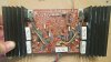
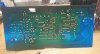
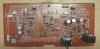
Take some photos of the driver and pre-driver boards of the mess up channel.
 
Left channel connected the relays, I was going to test with sound, when I stand the amp vertically on one of its sides and power up, relays did not connect.
Back to the horizontal table the Left channel do not connect the relays.
I wonder if some excess of thermal paste on the power transistors (silicone grease) is preventing to get the base and emitter properly connected ?
I will take some shots. Thanks
 
Left channel connected the relays, I was going to test with sound, when I stand the amp vertically on one of its sides and power up, relays did not connect.
Back to the horizontal table the Left channel do not connect the relays.
Sounds like a bad wire/solder connection.
 
SOLVED !!
In the power supply board the transistor or thyristor that has a heat sink was not properly soldered
I started touching components till discovered. Thanks for your help. !
 
SOLVED !!
In the power supply board the transistor or thyristor that has a heat sink was not properly soldered
I started touching components till discovered. Thanks for your help. !
:banana::music:
 
Thank you, now a new little problem:
On the Right channel I can not adjust idling current/BIAS nor DC offset.
Measuring between CT(-) and NE(+) always value is 0.02mV no matter what position is the variable resistor.
For DC balance measuring between CT(-) and E(+) always -OL shows my digital multimeter but there is a point in the variable resistor makes the relay to disconnect.
Any suggestion ?
 
Look over solder connections on the pre-drive sheet. Especially the TO-126 and TO-220 transistors solder connections.
 
Hi, Yes, the +/- 65V adjust fine.
I re-solder several thin transistor connections, and now the CT NE keeps -0.00 mV, and the CT E gives constantly -180mV no matter the position of the variable DC offset resistor.
I have not tested yet the sound.
 
Measure the voltage around TR414 and 416 -- They are two TO-220 case style transistors fastened to the large heatsink.
B -- ?
C -- ?
E -- ?
 
Last edited:
I will check, thanks. I tried to test sound and no signal on output, VU meter does not light up. I don't know if short circuited something or burned any component. I will try to remove excess of tin.
 
Sound is back !

Sorry, I can not identify the transistors you indicated.
According to the manual TR-220 is a small black transistor
 
Back
Top Bottom