sae-7125
Super Member
the first amp seemed somewhat straightforward and was a 120v model, no broken output terminals. amp number two originally had a smoked channel although no chernobyl nor 3 mile island event transpired (yet, night is still young) perhaps a windscale.
interesting info about the above metaphor (word origin):
 academickids.com
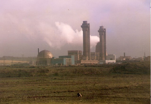
 en.wikipedia.org
the bulk of this diagnostic evaluation will be in regards to amp #2, international model with voltage selector, since amp #1 had minimal issues and went back to its owner after some basic updates. obviously two different part number mains transformers between the two amps.
first step involved the usual glue removal and associated splatter on nearby components/jumpers. updated c157/158 and r141/142 and then diode checked the heat sinked components. tr135/137 (2sa1106) had base to collector shorted and r149/151 (2.2r) measured in the meg even though physically/cosmetically looked oem/new.
slowly replacing various diodes and zeners helped stabilize the channel to the point of not stuck in protection mode. the amp has been chained to dim bulb and variac (100v mains) until the final gremlin has been dealt with (unstable channel bias). dc offset for each channel is 15mv or less (right +13, left -15). when left channel bias is set to minimum the emitter resistors measure 10mv front and 13mv rear across each pair as shown in the service manual, should be zero mv. activating the "class a" cooker mode shows a roller coaster response going down a few mv then up several mv and back down a few mv. the right channel responds normal, active = up and stable new bias set point (circuit controlled/regulated).
if the left bias is too high when powered on then protection mode stays active even though dc offset is stable/low. adjusting the new bias pot from minimum to almost middle position helps to reduce the bias enough for protection mode to turn off. the amp plays fine in terms of audio output albeit limited by dim bulb ampacity.
a few more original low level transistors to replace and some diodes, after that it will be LCR interrogation of fusible resistors if needed. black gate capacitors removed/updated with fresh components especially since some measure low and have esr creeping up.
the hunt for stability and optimal functionality continues...
.
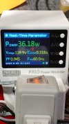
reference numbers from the first amp (120v model). still on dim bulb (limited to 75w using two 40w bulbs in parallel). dc bias: ~4mv (dim bulb) = ~10mv (no bulb. full mains). i should have captured full mains numbers, would have been more useful to others...
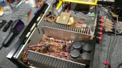
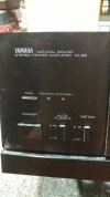
first amp
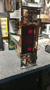
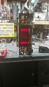
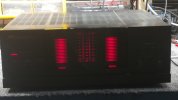
amp #2, international voltage selector, faceless and playing music on dim bulb (variac 100v mains)

.

output devices and new pot (left channel)

left channel new components, photo technically upside down.
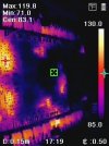
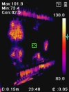
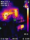
thermal scan (amp 2), potential circuit imbalance tr119 (schematic, 2sa1306) although pin voltages match schematic and right channel tr120.

top side of pcb.
interesting info about the above metaphor (word origin):
Chernobyl - Academic Kids
Windscale fire - Wikipedia
the bulk of this diagnostic evaluation will be in regards to amp #2, international model with voltage selector, since amp #1 had minimal issues and went back to its owner after some basic updates. obviously two different part number mains transformers between the two amps.
first step involved the usual glue removal and associated splatter on nearby components/jumpers. updated c157/158 and r141/142 and then diode checked the heat sinked components. tr135/137 (2sa1106) had base to collector shorted and r149/151 (2.2r) measured in the meg even though physically/cosmetically looked oem/new.
slowly replacing various diodes and zeners helped stabilize the channel to the point of not stuck in protection mode. the amp has been chained to dim bulb and variac (100v mains) until the final gremlin has been dealt with (unstable channel bias). dc offset for each channel is 15mv or less (right +13, left -15). when left channel bias is set to minimum the emitter resistors measure 10mv front and 13mv rear across each pair as shown in the service manual, should be zero mv. activating the "class a" cooker mode shows a roller coaster response going down a few mv then up several mv and back down a few mv. the right channel responds normal, active = up and stable new bias set point (circuit controlled/regulated).
if the left bias is too high when powered on then protection mode stays active even though dc offset is stable/low. adjusting the new bias pot from minimum to almost middle position helps to reduce the bias enough for protection mode to turn off. the amp plays fine in terms of audio output albeit limited by dim bulb ampacity.
a few more original low level transistors to replace and some diodes, after that it will be LCR interrogation of fusible resistors if needed. black gate capacitors removed/updated with fresh components especially since some measure low and have esr creeping up.
the hunt for stability and optimal functionality continues...
.
reference numbers from the first amp (120v model). still on dim bulb (limited to 75w using two 40w bulbs in parallel). dc bias: ~4mv (dim bulb) = ~10mv (no bulb. full mains). i should have captured full mains numbers, would have been more useful to others...
first amp
amp #2, international voltage selector, faceless and playing music on dim bulb (variac 100v mains)
.
output devices and new pot (left channel)
left channel new components, photo technically upside down.
thermal scan (amp 2), potential circuit imbalance tr119 (schematic, 2sa1306) although pin voltages match schematic and right channel tr120.
top side of pcb.