• The move to the new server is done. There are some software and database maintenance updates in process. This has us passing the hat around to help out. We appreciate any donations. Seriously, even a dollar helps. The payment page may be found here - https://www.audiokarma.org/support.html

Yamaha M-65 protection mode - seeking help

tocomplero

New Member
Hello all!

I have a M-65 that recently went into protection mode and won't get out of it. I'd really appreciate some guidance on getting it fixed.

I'm not nearly as experienced as most of the people who post here are, but I have tools and the schematics and I'm willing to learn. I've never fixed something as complex as this but I'd like to try and see if anyone here can guide me through.

I already tried removing the black plastic cap for the speaker relay but nothing looks or reads wrong there. Also tried the bias adjustment but there's no current there at all, so I reckon the problem comes from earlier in the circuit.

Sorry for being so vague with all this but I'd like to give it a try and learn on the way before sending it to a shop :)

I've read (and am still reading) through several of the threads that already exist on the matter but I haven't found a solution yet. Thanks!
 
Register to hide this ad
First we need to check for any DC at the two amplifier outputs. Should be real close to zero volts. A few millivolts is OK.
 
( Correction to previous incorrect -- deleted-- post ) BTW the procedure is correct if you use the "Adjustment Points diagram" right below the written procedure.

Sooo..
Also tried the bias adjustment but there's no current there at all,
Did you check both sides ( channels ) ?
 
Last edited:
First we need to check for any DC at the two amplifier outputs. Should be real close to zero volts. A few millivolts is OK.

The testing points for these two DC voltages have to be before the protect relay. The easiest is to scratch some enameled coating off of each one of the zoebel networks air coils. ( L101 and L102 ) check for any DC voltage on these two coils (inductors). The voltages could be either negative or positive. --Note which polarity !
 
Last edited:
How to voltage check if your not sure....
1. With your black test lead fastened to one of the speaker " A " black binding post (ground).

2. Then probe the testing points with your red test probe.
 
thanks so much avionic! can't believe I got a reply from you this fast. really appreciated :)

I'll do everything you suggested and report back.
And yes, I tried both bias adjustment channels.

Cheers
 
So!
I built the dim bulb tester, hooked up the amp to it and the bulb lights up right away when power goes on. It lights up well for a second when power goes on, then dims down (bulb is 40w).
Scratched a bit of enamel on each coil (L101 and L102), put the black probe of the tester on the speaker output, then the red probe on the coils. Both coils read around -56 volts.
 
Both coils read around -56 volts.
OK . We need to check and see if there is + 56 going to the NPN output transistor collectors from the power supply. Find R141 fusible resistor( 22Ω ) should see +56 vdc on both ends of this resistor. If it doesn't have close to the same voltage at both ends. It is bad...
 
Last edited:
upload_2023-1-11_20-47-10.jpeg

Here is the location of R141 and 142.. These will be a light green color on your unit.

R142 will have -56vdc at both ends..
 
Last edited:
Find your 8 output transistors. (TR131 thru TR138 ) Measure the DC voltage on the 8 collector pins. ( center pin )
 
hello!

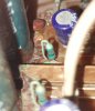
so I definitely wasn't measuring the resistors correctly. I tried to test both ends but getting the probe to touch the metal and not the light green layer was a little difficult. I was testing resistance to get those 22ohm and, in the process, one of the ends of R142 broke and left this bright green powder residue. looks like rust or something similar? I already cleaned most of it with a q-tip with a bit of isopropyl alcohol so you can't really see it in the picture. I didn't force it that much while testing, it was probably already damaged from before. I get not resistance reading either so I think it's safe to say it needs to be replaced. R141 is fine and reading -56v at both ends, as well as 22ohm.

2023-01-14 13.59.00.jpg

I also tested the output transistors and the readings are:
TR131 34v
TR132 34v
TR133 34v
TR134 34v
TR135 -59v
TR136 -59v
TR137 -59v
TR138 -59v

I imagine I have to order a 22ohm resistor, take the board out and replace the faulty part?
 
It's probably bad form for me to intercede @avionic. I just happen to be drinking coffee and reading forums and have been where you are at several times...

Definitely have to replace that resistor. There is a lot of glue there that should be cleaned. It corrodes the components. There may be a chance that the root of your problem may be that that lead on the resistor was already broken or corroded enough to not be functioning. You don't need to remove the board to do this, but you should remove all the component affected by the glue, and replace them while you are at it. That 22 ohm resistor sees a lot of current on power on to charge the 1000µF caps C157 and 158, not all 1/4 W resistors can withstand that. That resistor being broken will put the amp in protection mode.

About the glue:
https://www.audiokarma.org/forums/index.php?threads/yamaha-m-series-and-glue.280088/#post-3432894
https://www.audiokarma.org/forums/index.php?threads/yamaha-dsbg-thread.345131/
 
Last edited:
Back
Top Bottom