Greetings!
I picked this amp up cheap, however it was sitting in a storage unit in the hot Phoenix, AZ weather for "at least 10 years". The amped worked though and sounded pretty good considering. I decided to restore the old girl and bring her back to her former glory. I did this in steps over time.
First I replaced the big 4 filter caps as they where super bulged up on the ends with 4 x 380LX333M050A082. After replacing them I used the amp a few hours daily for about a week with no issues and was really liking the sound of this thing. Sweet.
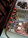
Next I replaced the binding posts in the back because I cant stand those types of connections and it was missing 2 of the screw on caps. After upgrading those to some nice 5 ways, I again used the amp a couple/few hours a day for about two weeks, no issues. Sweet.
Then I went ahead and replaced the small 30 or so capacitors on the board, mostly with nichicon UKT/UKA and some gold UFG. The amp sounded wonderful, better than my Denon POA-2400(still all original) and I decided to keep it as my main amp instead of the Denon.
After almost 2 weeks of daily usage one day I turned the amp on as normal and about 10 seconds later a horrible sound came through my speakers. I ran to the amp and turned it off then un pluged it from the wall, I didn't see smoke but I could smell it. The amp was now in protection mode. Not sweet....
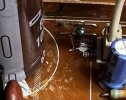
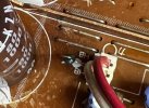
Took it to my bench and found that the R142 22ohm resistor on the right channel had burned up for some reason. I proceeded to test literally everything, all transistors big and small, all 8 small diodes, all surrounding resistors, etc. Nothing is shorted or anything that I can find that would cause this resistor to burn up. I read a few other topics here on AK of similar issue, but nothing conclusive as to what is causing this to burn up. I cleaned all the old glue(what a pain) from the nearby 1000/80 caps off the board, rails, and surrounding areas while doing the recap before.
I decided to replace it with a metal film 22ohm, not a flame proof one. The amp worked and sounded fine on a cheap test speaker, however whenever I would turn the amp on, a small poof of smoke would come out of the resistor along with a small flash. It would do this every time the amp was powered on but the amp would work. For about 5 mins anyway then the resistor would completely burn out and unit would go back in protect mode.
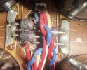
The only thing that seems to test kind of weird are the very large diodes near the back by the 4 large caps. While they all read around .44v, when you reverse the polarity of test leads when testing, the left ones go from .7v and climb up slowly while the right ones go from 2.8v and climb up slowly. This is the only out of norm thing I can seem to find here but I am not sure if this is something to be concerned about.
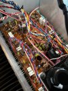
I went ahead and attached some pictures of those diodes, completed board after recap, and the upgraded terminals.
Sorry for the big wall o' text but wanted to give as much info as I could here. Any help would be greatly appreciated as I am beyond stumped. And frustrated
I picked this amp up cheap, however it was sitting in a storage unit in the hot Phoenix, AZ weather for "at least 10 years". The amped worked though and sounded pretty good considering. I decided to restore the old girl and bring her back to her former glory. I did this in steps over time.
First I replaced the big 4 filter caps as they where super bulged up on the ends with 4 x 380LX333M050A082. After replacing them I used the amp a few hours daily for about a week with no issues and was really liking the sound of this thing. Sweet.
Next I replaced the binding posts in the back because I cant stand those types of connections and it was missing 2 of the screw on caps. After upgrading those to some nice 5 ways, I again used the amp a couple/few hours a day for about two weeks, no issues. Sweet.
Then I went ahead and replaced the small 30 or so capacitors on the board, mostly with nichicon UKT/UKA and some gold UFG. The amp sounded wonderful, better than my Denon POA-2400(still all original) and I decided to keep it as my main amp instead of the Denon.
After almost 2 weeks of daily usage one day I turned the amp on as normal and about 10 seconds later a horrible sound came through my speakers. I ran to the amp and turned it off then un pluged it from the wall, I didn't see smoke but I could smell it. The amp was now in protection mode. Not sweet....
Took it to my bench and found that the R142 22ohm resistor on the right channel had burned up for some reason. I proceeded to test literally everything, all transistors big and small, all 8 small diodes, all surrounding resistors, etc. Nothing is shorted or anything that I can find that would cause this resistor to burn up. I read a few other topics here on AK of similar issue, but nothing conclusive as to what is causing this to burn up. I cleaned all the old glue(what a pain) from the nearby 1000/80 caps off the board, rails, and surrounding areas while doing the recap before.
I decided to replace it with a metal film 22ohm, not a flame proof one. The amp worked and sounded fine on a cheap test speaker, however whenever I would turn the amp on, a small poof of smoke would come out of the resistor along with a small flash. It would do this every time the amp was powered on but the amp would work. For about 5 mins anyway then the resistor would completely burn out and unit would go back in protect mode.
The only thing that seems to test kind of weird are the very large diodes near the back by the 4 large caps. While they all read around .44v, when you reverse the polarity of test leads when testing, the left ones go from .7v and climb up slowly while the right ones go from 2.8v and climb up slowly. This is the only out of norm thing I can seem to find here but I am not sure if this is something to be concerned about.
I went ahead and attached some pictures of those diodes, completed board after recap, and the upgraded terminals.
Sorry for the big wall o' text but wanted to give as much info as I could here. Any help would be greatly appreciated as I am beyond stumped. And frustrated