• The move to the new server is done. There are some software and database maintenance updates in process. This has us passing the hat around to help out. We appreciate any donations. Seriously, even a dollar helps. The payment page may be found here - https://www.audiokarma.org/support.html

Yamaha MX-1 Thread

The speaker Relays that I will be using are Omron G4W2212P-US-TV5 DC24. They are normally carried by Mouser and DigiKey, but are on back order at Mouser at the moment.

https://www.mouser.de/ProductDetail...GAEpiMZZMsF1ODjcwEocF9%2bQyXO85/0uscRNXS75As=
https://www.digikey.com/en/products...s-inc-emc-div/G4W-2212P-US-TV5-HP-DC24/765510

Mouser also has a G4W2214P-US-HP-DC24. As far as I can see the difference between the 2212 and 2214 is that one is sealed and the other not.
https://www.mouser.de/ProductDetail...GAEpiMZZMtGt%2Bn33CgIPxKJiRRLWidhma6eIBbmV9Q=

I have 1 misgiving about using these relays, and that is the following statement in the datasheet: " Do not use the G4W to switch micro loads less than 100 mA, such as in signal applications." In spite of that it looks like these relays are being used by many for this application and I haven't read any complaints as of yet.

When I have the old relays removed I will open them and inspect the contacts. If they are burned they will be discarded. If however they are only tarnished/oxidized I may consider trying to polish them for re-use.

While I have the amp apart I will be replacing the speaker binding posts. When I get that far I'll post pics and measurements. So far I haven't seen anyone else here with a MX-1 that has done that so hopefully that will be useful info for someone.

Cheers,
James
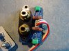
 
While I have the amp apart and am waiting on parts I decided to replace some resistors with low-noise types.

R78 &79 (470 ohm / 1/3w) are on the input daughter board and directly in the signal path. I had previously put Vishay SFR25 400mW resistors there. They have been replaced with Vishay RN70 1/2w.

DSC05624.JPG DSC05626.JPG

Cheers,
James
 
R19 & 24 are also directly in the signal path (100 ohm / 1/2W), in the input side of the muting section. I had also put SFR25 500mw there, now replaced with Vishay CMF60 Industrial, 1W. These and the 470 ohm parts were measured and sorted to under 0.5% tolerance.

DSC05627.JPG

Cheers,
James
 
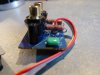
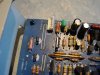
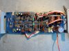
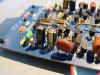
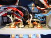
One thing that I failed to do the last time that I had the amp apart was to take some photos of the input/muting/V-Amp board. So here are some photos to correct that mistake.

DSC05629.JPG DSC05631.JPG DSC05632.JPG DSC05633.JPG DSC05635.JPG DSC05636.JPG DSC05637.JPG

Cheers,
James
 
Before getting to the speaker relays I have been working on the binding posts.

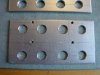
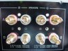
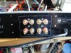
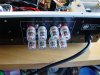
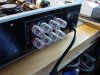
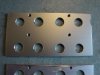
First, 2 photos of the back panel raw and removed from the amp.

A couple of notes.
1) Both L&R - are in the middle.
2) The mounting screw hole cutouts are 3.4mm in diameter.
3) The binding post hole cutouts are 16.6mm in dia.

DSC05638.JPG
DSC05639.JPG
This photo shows the back panel tipped down, so, the view is reversed from normal, upside-down. Note the horizontal shadow/dust that shows where the binding post block lower edge was. The circuit board is located directly under that shadow when the amp is assembled! There is very little-to-no extra clearance under that shadow line and a binding post mounting panel must end above that point. I measure 27mm from the center of the small lower mounting screw hole to the upper edge of the shadow. So to be safe I calculated my panel with a maximum of 25mm below that hole.

Cheers,
James
 
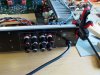
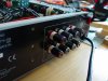
Next up are some shots of the stock binding post block and the buss bars connecting to the pcb, as well as how much space there is to work with. (Hint, not much).

DSC05640.JPG DSC05641.JPG DSC05642.JPG DSC05643.JPG DSC05644.JPG

My rough measurement of the amount of space between the back panel at the Speaker B Left posts and the relay is about 23mm. I will nail that down more accurately after I get the post block unsoldered.

Cheers,
James
 
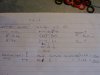
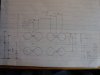
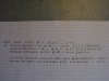
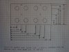
My rough notes and measurements photographed, followed by the drawing that I made for the new mounting panel for the posts.

DSC05663.JPG DSC05664.JPG DSC05666.JPG DSC05668.JPG

Note that the original post block measured 50mm H x 90mm W. I chose 50 x 100mm. There is room for a wider panel, and as long as the extra is on the upper end the panel can be taller, 60mm would be no problem, 55mm might have been better than what I made.
Note also that the vertical centerline positions that I chose on the 1st prototype were 10mm/25mm/40mm/48mm. That put the upper mounting screw holes right at the upper edge of the panel. Since I had already cut several pieces out of some scrap that I found at work I shifted the centerlines down by 1mm. This effectively moved the entire panel up by 1 mm when it is installed, so, also increasing the lower clearance above the pcb by a bit of extra safety margin.

With vertical positions of 10/25/40/48mm there is 2mm of clearance between the lower edge of the mounting plate and the PCB.
With the 9/24/39/47mm centerline position that I used there is 3mm of clearance.

Cheers,
James
 
Last edited:
The 2nd and 2rd panels that I cut. They don't look beautiful, just some 2mm and 3mm thick scrap aluminum that I found at work. I will be using the 3mm thick part.

DSC05645.JPG DSC05646.JPG DSC05647.JPG

I don't have a lot of sophisticated tools available. To mark the raw panel I took my dial calipers and set them for each centerline measurement, locked the jaws, and transferred the measurement to a sliding 45/90° angle, and then scribed the line with a fine scribe. Scribing the lines has the benefit of leaving a slight depression where they cross, making for a very precise positioning of my centerpunch.

The small holes were drilled to 2.5mm and tapped for M3 screws. The large holes need to be 10mm. I used 10mm on my first prototype, and everything fit, but I moved to a 10.2mm drill on the 2nd and 3rd panels to give a little extra wiggle room when fitting everything in place.

Cheers,
James
 
So, the binding posts. I bought 2 varieties of Dynavox posts. Before showing them there is another detail to go over.

The posts come with a clear plastic insulator ring, and I measured them at 20.5mm outside diameter. The panel cutout is only 16.6mm, and I need the posts to be able to pass through the back panel of the amp when already mounted and secured to the new mounting panel. There is simply no room, and I have no interest in trying, to solder the connection wires to the pcb after the entire panel is mounted.

I went through this with my M-70, and used the rather crude method of mounting the rings to a bolt, sticking that in a drill press, and slowly filing the rings down small enough to pass through the back panel of the amp. Since then our metal lathe at work has been repaired and so this time I was able to turn the rings down to 15.5mm on the lathe. There is not a lot of material left, but enough.

DSC05654.JPG DSC05655.JPG DSC05656.JPG

Cheers,
James
 
So, finally, the binding posts.

Dynavox sells some nice posts, the clear plastic ones are seen all over the place under all kinds of different names, as well as a huge amount of Chinese copies. That is what I generally use for speakers, and that is what I used for my M-70.
But they also make some nice 15.5mm diameter black plastic/brass posts and that is what I wanted to use here.

But.
The stems are too long to use here, 25mm and I have less than 23mm of space to work with. Now, with all of those clear plastic type posts the outer screw cap is removable, and I was hoping that I could just buy some of the very short clear posts and just swap the brass studs/stems with the black ones. So I bought a full set of each.

Alas, it turns out that the black screw-caps are staked to the post or something, and they are not removable. So the only way that I might be able to get them to work would be to add some spacers to the outside so that the do not penetrate into the case so far.
But.
The posts are already quite tall/long, and the amp is already quite deep, enough so that I don't think that I will have space on my shelf to use the black posts.

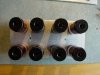
So, finally, a few photos of the black posts that I probably can't use mounted to the prototype panel that I won't be using. Did I mention that I really like these binding posts?

DSC05649.JPG DSC05650.JPG DSC05651.JPG DSC05652.JPG DSC05653.JPG

Cheers,
James
 
On to the Mission Backup plan.

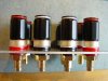
The short clear posts are still nice. Here are some shots of them, free and mounted to a plate, and the assy in position in the back panel.

DSC05658.JPG DSC05659.JPG DSC05660.JPG DSC05661.JPG DSC05662.JPG DSC05669.JPG

As you can see, everything lines up and I am confidant that the measurements provided in the drawings above are accurate and will work. Not shown, but the mounting screws were test fitted and actually fit. :)

That's all for today.

Cheers,
James
 
Last edited:
Here are a few photos of the long black posts temp fit to check clearances.

DSC05684.JPG DSC05685.JPG DSC05686.JPG DSC05688.JPG

Even with 2 extra 1.5mm plastic spacers behind the posts there is very little room between the lower right post and RY201. Ant the posts would be so long behind the amp that they would hit on the back wall of my stand by the time that I have the amp positioned safely.

So I won't be using these posts. Sad, because I really like them.

Cheers,
James
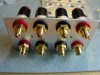
 
Here are a couple of shots of the short stem (20mm) posts in place. This is without any extra spacers behind the posts. I will in fact be using 2 extra spacers on the lower set of posts.

DSC05695.JPG DSC05696.JPG

Also, I did measure the amount of space between the inside face of the back panel and the Speaker-B relay. It is 23mm.

Cheers,
James
 
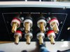
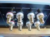
The posts that I will be using test fitted in place before tightening the nuts on the shafts.

DSC05703.JPG DSC05705.JPG DSC05706.JPG DSC05707.JPG

The leads are 1.5mm² silver plated OFC copper.

Cheers,
James
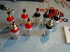
 
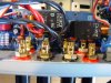
The Yamaha terminal posts have a 0.012µF film cap soldered between + & - on the Speaker-A posts, and another cap from - to the PCB. I will be re-using the caps and they are now soldered in place.

DSC05708.JPG DSC05709.JPG DSC05710.JPG

Cheers,
James
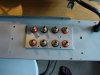
 
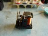
I de-soldered both speaker relays and opened them up. The contacts showed no signs of burning or pitting, just a slight discoloration but still shiny.

I elected to polish them with a Deoxit soaked piece of paper (no sanding here!). After that they were cleaned with acetone and re-installed. The contacts look so good that I'll take my chances and keep on using them.

I couldn't get a good shot of the contacts but here are a few photos of what the relays look like inside.

DSC05678.JPG DSC05681.JPG DSC05683.JPG

Cheers,
James
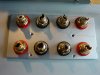
 
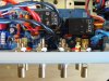
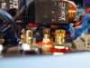
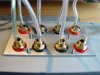
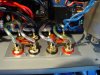
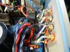
Yesterday the new terminals/posts were soldered in place.

The wire ends were tinned with solder and then squeezed flat to 1.1mm in my vise, and then trimmed in width. That made them a drop-in fit in the pcb slots. The wires were cut as short as I could while leaving enough to work with and have enough to flex them around to position them.

DSC05711.JPG DSC05712.JPG DSC05713.JPG DSC05714.JPG

Cheers,
James
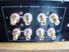
 
There was enough room to add a self locking nut to the upper terminal plate mounting screw. Also, the washers that I used under the screw heads are slightly conical and act as lock washers.

DSC05721.JPG DSC05727.JPG

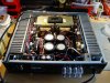
After that the amp went on the dim-bulb-tester as a last precaution for the first power up and passed the test. It is all buttoned up now and tomorrow it will go back into the system.

Cheers,
James
 
Back
Top Bottom