• The move to the new server is done. There are some software and database maintenance updates in process. This has us passing the hat around to help out. We appreciate any donations. Seriously, even a dollar helps. The payment page may be found here - https://www.audiokarma.org/support.html

Yamaha p2200 help

Wiley183

New Member
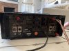
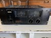
Hi all. I just picked up a Yamaha P2200 that someone put out on the curb. Hauled it home on the back of my baby stroller as I was out for a walk with the fam. I took it home and tried to hook it up to my Marantz 2330b pre out with no sound however, I get a slight pop about 8 seconds after shutting the power amp off.

I’m a guitar player so I decided to try and hook up my Marshall jmp-1 pre amp and again experienced the same results. No sound but a slight pop 8 sec after shutting it off. I tried 1/4in to xlr, rca with a 1/4 adapter and finally 1/4 to 1/4 with my guitar rig with no luck. Why are their two 1/4 inputs for bot A and B? What else can I do to tell if the amp is toast or just not connected correctly? Thanks
 

Attachments

  • F88EB967-F936-4672-974D-F0E2F4AFDFE0.jpeg
    F88EB967-F936-4672-974D-F0E2F4AFDFE0.jpeg
    109.9 KB · Views: 26
  • 53C20D09-3014-4DBD-89C6-C4B94BAF5D23.jpeg
    53C20D09-3014-4DBD-89C6-C4B94BAF5D23.jpeg
    108 KB · Views: 21
Register to hide this ad
Turn the input attenuators fully CW and give it another go.. Welcome to AK.. BTW.
 
Turn the input attenuators fully CW and give it another go.. Welcome to AK.. BTW.
Thanks for the welcome and the note. I should have mentioned that I did have the input attenuators up during testing but not all the way. I’ll give it a go with them up all the way. I’m just getting nothing.
 
the amp is toast
Most likely..Needs a service tech..Unless you are capable of T-shooting the malfunction. Both channels out? Most likely a power supply issue.
 
Last edited:
Yes you should have..
Now you know why it was on the curb..
Most likely..Needs a service tech..Unless you are capable of T-shooting the malfunction. Both channels out? Most likely a power supply issue.
At this point I absolutely agree about the service tech. Yes, both channels give me nothing. Thanks for the pro tip on the power supply and responding to the post. Seems like a decent amp and worth fixing if it’s a power supply. Thanks again -Adam
 
@avionic is the Yamaha guy. He can fix it if you get stuck.

If you are planning to fix it yourself, let us know and we can walk you through the equipment needed. I'm assuming you found the schematic and know how to read it. Take a lot of pics and post your plan.

Also, let us know where you are. sometimes an AK tech close by can give you a hand.
 
@avionic is the Yamaha guy. He can fix it if you get stuck.

If you are planning to fix it yourself, let us know and we can walk you through the equipment needed. I'm assuming you found the schematic and know how to read it. Take a lot of pics and post your plan.

Also, let us know where you are. sometimes an AK tech close by can give you a hand.
Wow that’s fantastic news and very kind of you to let me in on help. I’m in Reno, NV. I did do HT install for 10 years so I’m not completely new to hooking things up however I’m a bit of a rookie when it comes to opening up electronics. I’m fairly handy and can solder. Can you suggest where I can buy a power supply to start? I’m willing to give it a whirl especially if I have some help. Thanks again!
 
I haven't worked on a p2200 (only a couple p2250). I'll try to help.

The first thing I'd do is to narrow down the problem.

with the amp unplugged and nothing connected to it (both inputs and outputs disconnected) and gain controls full on, turn on amp and measure the DC offset at the speaker terminals. I don't know if there is some kind of speaker protection that will get in the way (I haven't looked).

black DVM lead to black banana, red DVM lead to red banana.

post results.

you want something less than 100mV. Lower the better but not critical.

if you see something like the B+ (you downloaded the schematic and studied it right?), one (or more) of the outputs are blown. We will need to discuss next steps.

feel free to post your test equipment (DBT, signal generator, scope, ...). It kind of helps determine troubleshooting direction.

hopefully @avionic will post some ideas too.

the pics I found on line show a cramped chassis. I don't know how easy this will be. I hope someone with more experience will chime in.
 
Each amplifier assembly has three test pins CT,PE and E

E is chassis ground

CT is amplifier output

PE is emitter resistor test point for bias

Voltage between CT and E is your center point or DC offset. No adjustment. Should be as close to zero volts .

Voltage between PE and CT is your bias voltage adjust to 10 mv. ( see service manual for the correct trimmer adjustment)

For now measure the voltage across E and CT....Post results....
 
Back
Top Bottom