• The move to the new server is done. There are some software and database maintenance updates in process. This has us passing the hat around to help out. We appreciate any donations. Seriously, even a dollar helps. The payment page may be found here - https://www.audiokarma.org/support.html

Yamaha PC2002M Missing +80Volt

omri617

Super Member
Hi there
Got this nice Amplifier.
It stays in protection.
All fuses are good.
Measured the filter capacitors and there is +90V/-90V
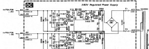
But at the DC board I get no +80V as manual indicates.
Took D502 out and it’s not open.
Also checked and replaced TR501and I still get
Emitter 118V
Base 119V
But Collector gives 2.5V

Also TR505 checked and it’s not shorted
I’m trying to know why I get no +80V
I even pulled all sockets that go to the power boards, still no +80V.

Any help would be greatly appreciated
 

Attachments

  • IMG_3032.jpeg
    IMG_3032.jpeg
    258.3 KB · Views: 21
  • IMG_3047.jpeg
    IMG_3047.jpeg
    122 KB · Views: 24
  • IMG_3079.jpeg
    IMG_3079.jpeg
    277.6 KB · Views: 21
Register to hide this ad
Check zener ZD501, looking for a short

edit TR509 b/c/e voltages to GND would help localize fault
 
Last edited:
ZD501 gives 0.5V when checked across
With power off, MM in diode test mode, red probe to cathode, blk to anode, don't want beep/low value. Guiding voltages suggest a 6.2V zener.

TR509 to GND

E -0.07
C 1.7V
b 0.05
I wouldn't say conclusive...
I would have liked TR509Vbe to be 0.5V on account of D506, also zener cathode (-0.07V) is not close.

If you want to take a punt, replace ZD501 and TR509, thinking zener 80/20 probability split
 
With power off, MM in diode test mode, red probe to cathode, blk to anode, don't want beep/low value. Guiding voltages suggest a 6.2V zener.


I wouldn't say conclusive...
I would have liked TR509Vbe to be 0.5V on account of D506, also zener cathode (-0.07V) is not close.

If you want to take a punt, replace ZD501 and TR509, thinking zener 80/20 probability split
Diode test :
1.15
Reversing the proves it give 0.7

Zd501 I replaced between the other side (negative) and it’s the same.
TR509 and TR503 sc1885 replaced with new 2383 and no change
 
Last edited:
Also checked and replaced TR501and I still get
Emitter 118V
Base 119V
Plz double check this, need Ve > Vb and Vbe=0.6V or so.
Diode test D504 and D505, red probe anode, looking for about 1-1.2V
Check those 3 x 33k's between D504 and D505, not open

Measure voltage at D503 anode expect -114Vdc abouts

Measure TR502 b/c/e to GND, need Vbe=0.6V

Yeah, I missed the point that the +ve and -ve rails are connected/tracked via that branch
 
Tested again

TR501 (A970)
E 117.5
C 1.6
B 117.1

TR503 (SC2383)
E 1.18
C 118
B 1.64

TR505 (MJE 15034G)
B 1.16
C 118
E 0.6

TR507 (KSC1845)
E 0
C 1.6
B 0.6

TR509 (2SC2383)
E 0.04
B 0
C 1.6

No voltage almost at the ends of either Diodes
ZD501
D506

All resistors were tested out of circuit all in specs except IP33 which I replaced.
Which has only 0.6V at one end.
 
  • Like
Reactions: mbz
Voltage of 501 when probes are on emitter and base is :
0.58V

D504 red probe on the “black half” of the diode gives 1.2V, other way it gives 0

D505 same values (it’s the other rail voltage?)

D506 0.56V both ways no matter which probe on cathode or anode

ZD501
1.15 red probe on cathode
0.55 red probe on anode

D503
Anode to GND -119 (I Live in 220V region)

TR502
E -118
C -79
B -117.7

Vbe of it is 0.56V
 
  • Like
Reactions: mbz
Thanks for the measurements.
TR501 Vc is a problem, Vbe is in the ballpark so either TR501 is faulty or something downstream is dragging this voltage down, eg TR509 and ZD501, but measurements suggest these are off.

I'd replace TR501

edit measurements shows TR501 Vbe kinda ok, if replacement doesn't resolve then measure actual TR501Vbe.
D504 (1.2V) looks good
 
Last edited:
Back
Top Bottom