
• The move to the new server is done. There are some software and database maintenance updates in process. This has us passing the hat around to help out. We appreciate any donations. Seriously, even a dollar helps. The payment page may be found here - https://www.audiokarma.org/support.html

Yamaha R-9 - Strange bias and offset issue

Shrugg

Active Member
Hello all, I am getting some very strange voltages on my Yamaha R-9. After testing it both on headphones and speakers and verifying that it sounded ok, I measured the offset and bias. For the offset, the left channel was a solid 18 mv, but I was getting a strange fluctuating voltage on the right channel, hovering around 40 mv, but going up and down quickly as much as +-20 mv. However, when I plugged my headphones in, it quickly dropped to zero mv. Is it just a phantom voltage, or something more serious?

I then checked the bias for both channels. Even after checking cable continuity and switching meters, I got 0 mv of bias on both channels :wtf:. It only rose to 0.5 mv when I switched on class a. So what gives? The amp sounds ok on my headphones and speakers. Is it something to even worry about?
 
Register to hide this ad
Did you try and adjust the bias as per the service manual? Does the bias respond to trimmer adjustment on either channel?
Normally means something is not quite right, eg, transistor, emitter resisters, solder joints, the fact that it sounds ok is
somewhat puzzling, maybe crank up the volume on some cheap speakers (if possible)
 
I already twiddled the trimpots, made no difference. I checked for any noise on both channels, but could not hear any, it was dead silent. I guess I'll try cranking it tomorrow, as Its too late for me tonight, but first impressions showed that it sounded ok. Anyways, my cheap speakers can only handle about 5 watts, so I may try using a load resistor in series with the speaker, if that doesn't cause any issues.
 
Try to dig out the service manual.
Normally the bias transistor, controls the dc voltage at the outputs (via the drivers). This is done for both the positive
and negative half of the amp, so the voltage at the emitters should vary slightly. No reponse to trimmers normally
means something in the chain is "broken" (could be a solder joint). May need to take voltage measurements to track down.
You could live with it but it shouldn't be sounding any good at volume in this case.
 
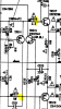
You could try measuring dc voltage at TR518base (+1.1Vdc) and TR520b (-1.1Vdc).
Don't probe transistor legs, probe connected part, eg R660 and R528. Voltages should vary
slightly with trimmer adjustment
 
You could try measuring dc voltage at TR518base (+1.1Vdc) and TR520b (-1.1Vdc).
Don't probe transistor legs, probe connected part, eg R660 and R528. Voltages should vary
slightly with trimmer adjustment

Just some potential noob questions. First, did you mean tr517b , and should I measure the voltage in parallel with the resistor or should I measure it relative to ground?
 
TR517, TR519 are for the left channel, TR518 and TR520 (ie, even numbers) are for the right channel.
Since this is happening on both channels you can test either/or both. Require voltage at transistor base, black mm probe
connected to chassis/ground. As mentioned above probe at connected resistor to avoid slippage/short. Better yet would be to
use mini-grabbers etc...

upload_2019-3-29_18-42-4.png
 
Back
Top Bottom