• The move to the new server is done. There are some software and database maintenance updates in process. This has us passing the hat around to help out. We appreciate any donations. Seriously, even a dollar helps. The payment page may be found here - https://www.audiokarma.org/support.html

Yamaha RX-596 completely dead - and I'm stumped

tommch

New Member
So before I float this out to sea and set it on fire so it can go out in a blaze of glory, I thought I'd ask to see if anyone has run into a similar problem...

Yamaha RX-596 receiver won't power on at all. No relay click, no nothing. Here's what I've done and checked so far...

- The Sub power supply has DC going out to the operations board, although it seems high at 15.7V.
- Pretty much everything on the Operations board is reading lower voltage than expected, in round numbers maybe about 3V less than what's published in the service manual.
- Main transformer checks out OK for continuity
- I've gone through the protection and regulator areas and have checked pretty much everything and all seems ok. I might have set a personal record for pulling components on this one :-)

I'm obviously missing something but am stumped at this point. Anyone tinkered with one of these before?

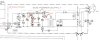
Uploading what I see on the sub power supply board for reference...

Thanks,
Tom
 

Attachments

  • RX-596 Sub Power Supply.jpg
    RX-596 Sub Power Supply.jpg
    60.4 KB · Views: 29
Register to hide this ad
0.05V at the base of Q140 isn't gonna close the relay. Take a look for a dead capacitor in the 5V system somewhere in the control section.

Those two diodes are suspect as well, although usually they don't cause funny voltage (unless you have a lot of AC on the DC 12V line).

The problem with this style of equipment is that the 12V system is ALWAYS powered on if the plug is in a live outlet, and 15 years down the road the electrolytic caps fail, leaving the unit completely unresponsive because there is no 5V DC on the computer. Significant AC causes it to flip on and off at 120Hz....
 
0.05V at the base of Q140 isn't gonna close the relay. Take a look for a dead capacitor in the 5V system somewhere in the control section.

Those two diodes are suspect as well, although usually they don't cause funny voltage (unless you have a lot of AC on the DC 12V line).

The problem with this style of equipment is that the 12V system is ALWAYS powered on if the plug is in a live outlet, and 15 years down the road the electrolytic caps fail, leaving the unit completely unresponsive because there is no 5V DC on the computer. Significant AC causes it to flip on and off at 120Hz....

Thanks for the tips on that. Never really considered the impact of 12V always on and the associated wear and tear. Makes perfect sense though. I'll swap out the old caps on the Operation board and see what happens. Voltages I've checked in the Regulator area seem the be about 3V low - in the 2 range instead of the 5-ish range. By the time things come out of the Control chip, the relay pin spits out like .7 when you press the power button and only about .4 when idle.

I'll check the AC level as well - I definitely would not have thought of that :-)
 
Bad filter caps let AC ripple onto the DC buss, which isn't good for the CPU. Will also read as "average" of the voltage swing as DC, so 3 V instead of 5V to me indicates dead caps (without them in circuit it would show up as 2.5V or so).

Probably come back to life with new caps and stable 5V and 12V.
 
Update: the mystery continues... This dual transformer design is so interconnected it's continuing to kick my butt. I'm convinced it has to route through a substation in Lichtenstein for permission from the Postmaster General before it'll turn on. Since the last post, my parts came in and I have:
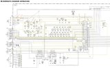
- Replaced all caps on the Operation board (schematic attached)
- Replaced the main filter caps
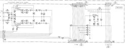
- Checked and replaced some of the possibly relevant caps on the Function Board (partial schematic attached)
- Pulled and checked all transistors on the Operation board
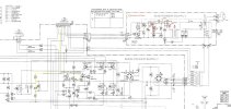
- Pulled the main board and did a pretty thorough check in the protection area. I only checked the caps with an ESR meter, have not yet pulled and closely examined them. Did pull and check relevant transistors. (see attached partial schematic)
- After parts changes, I've spot checked for AC and am not (yet) seeing anything significant. I did see some before though but it appears to be gone.

I have seen some changes. In short:
- The operation board is getting about 14.8 V but as you can see I'm losing lots of voltage all over
- The power circuit back to the low voltage transformer board and relay has increased a bit, now about 0.5V (still way too low, should be 4.8V I think to kick on the relay)
- When I hit the power button, pin 61 on the System Control IC changes from 0.37 to -0.91V

I'm running out of places to look. Any ideas?

PS - Yes, I'm spending way too much time on this but... A. I can't bring myself to convert it to a parts bin, B. Now it's a matter of honor and C. It's just kind of cool and I want to use it.

Thanks in advance for any ideas!
 

Attachments

  • RX-596 Main partial.jpg
    RX-596 Main partial.jpg
    79.7 KB · Views: 12
  • RX-596 Function Board Partial.jpg
    RX-596 Function Board Partial.jpg
    55.3 KB · Views: 12
  • RX-596 Operation Board.jpg
    RX-596 Operation Board.jpg
    105.1 KB · Views: 12
I would isolate the sub power board and verify you have correct power there, including the 5V computer VCC, and then start looking for what's pulling it down.

I had a KA-88 on the bench that had low voltage to the switching IC and no LEDs, and the filter cap for that circuit tested as a 0.9 ohm resistor. Replaced that and it came back to life just fine.

I really dislike that style of schematic, takes forever to find where things connect, but you will need to track down where the 5V from that sub power board goes and find where it's shorted to ground or where a cracked solder joint is causing poor connection, etc. I don't see a big filter cap on the sub board, I'm guessing, like the KA-88, it's somewhere else, probably a 1000 uF or so low voltage cap.
 
It looks like the equivalent filter cap you're referring to is C503 maybe. It's on the Operations board and is a 4,700uF / 5.6V cap. It tested OK but I went ahead and replaced it with a brand new one.

I've gone ahead and isolated the system to the small transformer power board and the operations board with the primaru IC that switches power on etc. No joy yet...
 
It looks like the equivalent filter cap you're referring to is C503 maybe. It's on the Operations board and is a 4,700uF / 5.6V cap. It tested OK but I went ahead and replaced it with a brand new one.

I've gone ahead and isolated the system to the small transformer power board and the operations board with the primaru IC that switches power on etc. No joy yet...
Any luck?
 
Back
Top Bottom