Max60Watt
New Member
Dear all,
I have a Yamaha RX-A3030 reciever that I have been working on for a while - it has an issue I can't figure out, so I hope that one of you can help me further!
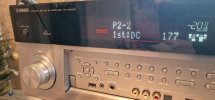
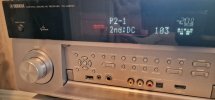
The SR (Surround Right) channel is outputting 0.85 VDC, while all the others read -1.0 VDC. The amp shuts off after a few seconds due to protection mode with the error DC PRT. I can however start it up in protection mode to do measurements.
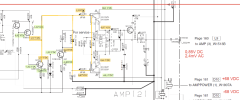
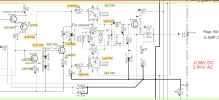
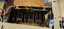
I have basic electronics understanding, I have tools, and I have repaired things in the past - but I can't figure out which part is the culprit in my receiver! I have narrowed it down to one channel and the part of the circuit is misbehaving. All resistors read specified values, all capacitors test ok (ESR meter) and I don't find any shorts in the transistors (also checked all the SMP). Diodes are testing ok, the zener I have not tested. I have measured voltage on differtent parts of the channel and compared with the other channels. One part of the circuit is reading positive voltage (see orange lines in the schematic below) where the others are reading negative. Would you know why? I have tried swapping the (medium sized) transistors around, resolder - no sign of cracking or broken connections.
Matching values are in green, deviating in orange (disregard the two yellow rings in the bottom circuit). Channel on top is the faulty one:

I will appreciate any advice, thank you.
Best regards,
Max
I have a Yamaha RX-A3030 reciever that I have been working on for a while - it has an issue I can't figure out, so I hope that one of you can help me further!
The SR (Surround Right) channel is outputting 0.85 VDC, while all the others read -1.0 VDC. The amp shuts off after a few seconds due to protection mode with the error DC PRT. I can however start it up in protection mode to do measurements.
I have basic electronics understanding, I have tools, and I have repaired things in the past - but I can't figure out which part is the culprit in my receiver! I have narrowed it down to one channel and the part of the circuit is misbehaving. All resistors read specified values, all capacitors test ok (ESR meter) and I don't find any shorts in the transistors (also checked all the SMP). Diodes are testing ok, the zener I have not tested. I have measured voltage on differtent parts of the channel and compared with the other channels. One part of the circuit is reading positive voltage (see orange lines in the schematic below) where the others are reading negative. Would you know why? I have tried swapping the (medium sized) transistors around, resolder - no sign of cracking or broken connections.
Matching values are in green, deviating in orange (disregard the two yellow rings in the bottom circuit). Channel on top is the faulty one:
I will appreciate any advice, thank you.
Best regards,
Max