• The move to the new server is done. There are some software and database maintenance updates in process. This has us passing the hat around to help out. We appreciate any donations. Seriously, even a dollar helps. The payment page may be found here - https://www.audiokarma.org/support.html

Yamaha YP-D4 Turntable speed issue

n3m3roth

New Member
Hi all,
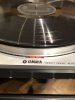
I'm having a bit of a problem with a YP-D4 direct drive turntable from Yamaha.
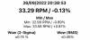
Though I set it up like in the service manual the speed wobbles a bit, it is more obvious on the strobe that moves bit left and right. I've also made a speed test with an app, maybe someone could give an opinion on that.
As I reconditioned this turntable I replaced almost all components except some small power transistors and resistors. The speed problem was from the start and replacing Zener, motor drive transistors etc. did not solved the issue.

Did anyone had a similar problem with such a turntable or any ideas where to start ?

Thanks !

Service manual :
https://www.vintageshifi.com/repertoire-pdf/pdf/telecharge.php?pdf=Yamaha-YP-D4-Service-Manual.pdf
IMG_5179.JPG File_000.png
 
Register to hide this ad
Welcome to AK.

I'd try to clean all the semi-open trimmers (VR-1...5) with contact cleaner, and then follow the SM routines (sections 1 and 2).
 
Thank you.

I cleaned the trimers and measured them, it seems all ok. Also I've replaced all the trimmers on the boards but it does the same.

So I was afraid that the motor was damaged in some way, opened it and measured the coils and Hall sensors and it seems one of the Halls gone bad :(

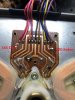
All is measuring identically except the two measurements done in the image (I took those measurements with all the wires from the motor control taken off) One Hall sensor measures 345Ohm and the other 270Kohm.

Does anyone know what kind of Hall sensors are those ? The red dot it tied to the ground. IMG_5183.JPG


IMG_5182.JPG
 
IDK, probably 40 y/o unobtanium TDK constant voltage analog hall effect sensors. I'm not sure what ohming the terminals on those HE's should give, or if the difference is significant. 20% tolerance isn't unheard of. It's more likely you succeed by verifying the wave form and adjusting it using VR-3/VR-4 (non-inverted op-amps input) and adjusting the offset of the inverted input using VR-5, than by a shotgun approach of replacing components. You should normally (unless the driver transistors or op-amps are shot) be able to balance the power to the coils using the SM approach.
 
Can I adapt some 4 pin modern hall sensors to all this ? like for example AH277A ?
As a last resort, when push comes to shove, you could probably try - but it's a bit of a gamble. The supply voltage range seems appropriate, and with that out of the way, analog HE's are not much different, but they have their quirks. For example, I don't think the red dot marks the ground lead. I'm guessing it marks the location of the sensor on the chip. When mounted on a PCB it needs to be oriented correctly relative to the S/N poles of the coils magnetic field. I'm not sure the leads of the replacement are long enough to jimmy rig on the PCB to get it right.

You're gonna have to check with a scope and adjust the wave form so it's equally offset (as per section 2 of the service manual), even if you manage to lay hands on the exact same NOS hall effect sensors, not to mention with some arbitrary replacement.
 
I had one of those years ago. Never put any effort into fixing it but it just wouldn't hold speed. "fixed" it by giving it away to someone who didn't care.
 
For example, I don't think the red dot marks the ground lead. I'm guessing it marks the location of the sensor on the chip.
I guess the gnd and positive leads are somewhat clear but I'm in doubt on the two outputs that are going to the IC1 IC ins. As in AN277 Pin 2 $ 3 (DO & DOB). But your right, it is a matter of testing out.
If I'm not mistaken I've seen something similar as hall sensors on many old VHS head drives, maybe someone could help a little with the NOS finding part.
Thanks !
 
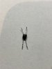
Now look what I've found in an old VHD head and some CD motors : IMG_5186.JPG
These types of hall sensors they all measure about the same value on the resistance or diode from each pin to the other and it is about 360 ohms. Something like the "good" sensor on my turntable motor. I guess the bad one is that with the kohms measurement.
 
Now look what I've found in an old VHD head and some CD motors
That was quick! Good for you - you're in luck! :)

Just make sure your TT speed fluctuations are related to those HE's. I'm not convinced you actually have a bad one. You may, but it would be a shame to replace the HE's and find out it the culprit is just some overlooked adjustment routine.
 
Yup, so that's why I deducted that that sensor is faulty. And after measuring the latest finds there are all in the range of 300-360 ohms.

I tried to put the motor driver on the scope but one part of the driver always gave me a "corrupted" wave signal, far from the one in the service manual but more like triangular and of a much less intensity.

For the first try I will try the old good one sensor on the left and a new find working one on the right to see what's happening :). I will try also with two smd 4 pin halls of the same type. Curious how all will work, or.. not :)
 
I tried to put the motor driver on the scope but one part of the driver always gave me a "corrupted" wave signal, far from the one in the service manual but more like triangular and of a much less intensity.
OK, good. Now you know for sure. Crossing fingers for that streak of luck of yours. :thumbsup:
 
Back
Top Bottom