• The move to the new server is done. There are some software and database maintenance updates in process. This has us passing the hat around to help out. We appreciate any donations. Seriously, even a dollar helps. The payment page may be found here - https://www.audiokarma.org/support.html

Yet another Heath W5M rebuild

Ben,

1) I can't remember right off hand what size solid copper wire I used for the input RCA signal and ground leads. You are correct, I covered them in heat shrink due to their close proximity to other leads/wiring. That is the same wire I used for the ground buss.

2) For the heaters, the really important wires are the ones that go to the output tube filaments. The 6CG7 filaments will work nicely with 18 or 20 gauge wire, as the length of the runs are short. For general hookup wire, I use 20 or 22 gauge Teflon insulation silver plated stranded wire. I like Teflon because of the very high temperature tolerance and I like silver plated stranded wire for it's low resistance/impedance.

3) For caps, resistors, sockets, etc I shop around and get the best price from numerous vendors. One time a certain vendor has the best price, say on a lot of 100 resistors. Next time it will probably be another vendor. Sorry I can't be of more help on that issue.

Again, feel free to ask any and all questions. As my first supervisor in the Air Force said to me: "The only dumb question is the one you didn't ask!"

Jim, AB0EZ
 
How is the schematic coming? Are you getting close to finishing this set? I am excited to see final pictures and a report on what you think of the sound. :)
 
I'm VERY close to finishing them. Once I do and I'm happy with the sound/performance etc, I'll publish the schematic.

If only work would stop interfering! I'm home, on average, one week out of the month. I've tried taking my projects with me and working on them in the hotels, but they kinda get upset with me when the smoke from soldering sets off the fire alarms!
 
W5M's were my friend's FIRST Hi Fi and I REALLY liked the sound !
The restoration you are doing here is OUT FREAKING STANDING !!!!

Can't wait to see the finished product & schemo !!!

MANY KUDOS TO YOU!
 
Thanks Vigman.

I'm doing a combination resto and upgrade on the W5Ms. I only wish I had a whole lot more spare time to do this in a timely manner. As it is, I'm mostly home on the weekends. Thankfully, I have a wonderful and GORGEOUS wife that puts up with me!
 
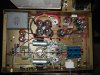
Had a little bit of time to finish up one of the chassis tonight. I'll finish up the second one tonight and do some preliminary checkout tomorrow. Once I think all is good, I'll ship them out to their owner and publish the schematic.
 

Attachments

  • DSCF81998.jpg
    DSCF81998.jpg
    115.8 KB · Views: 157
Hi John and thanks!

Typically I use 1M 1W and .01uF 630 or 1000V. The idea is some addition HF/RF filtering and I want the resistors to pull the cap charge voltages down quickly when the power is shut off.
 
I'm Turning Blue

I've been following this excellent thread, waiting patiently for the grand unveiling of the schematic and parts list so I could (finally) start on my pair.

So???
 
1) The 6CG7 is a more linear tube vs the 12AU7. The only thing you need to change is the filament wiring, regardless of any other changes, such as different plate & cathode resistors, etc.

2) You can use other than an oil filled (the big one in my post is a an oil filled cap, not a PIO cap). The main thing is make sure its a 4uF (or close) and rated at least for 600V.

3) All of the wire I use in my builds are Teflon insulated silver stranded wire.

Please feel free to ask me any other questions!

Jim, AB0EZ

Wondering how the build turned out.
 
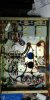
I bought my amps years ago and finally finished the first one last night. Sounds really nice!! Mine have the 16309 OPT.

I have the big vintage oiler caps for the first filter cap but couldn't use them as I went with KBG output caps in that space. I used a 10uF 900v film cap for the first filter cap and electrolytics for the rest. I added a CL80 thermistor at the AC in and a CL140 thermistor to the HV centre tap before grounding it to the first filter cap. I brought the filament centre tap to the output tube bias supply (pin 8 at one of the KT66's).

Tubes are new production Gold Lion KT66, RCA and GE 6CG7, and potato masher 5R4wgb.
 
Congrats Tom.
I had a pair of those and indeed, their sound was superb. Really nice amp.

I don't know if you did it or not, but make sure that the second pair of coupling caps 1uF 400V you used are in fact rated for 600V.
At startup, these takes a beating and start to leak, resulting in catastrophic failure of the output tubes/OT.

Cheers,
Brice.
 
Thx Brice. Its pretty scary to think they used 400v (& 450v) caps in these and many other tube amps which have well over 400v B+. This amp has 480vdc at the plates.

I used 630v K40's between the 6CG7's, and the KBG's are 600v.

And I'm using Gordon W's stupid simple preamp .... thx Gordon! I added a mono output when I built it. It's primary use is to enjoy my numerous orphan vintage mono amps. I drag them outside on a nice day and listen while grilling and hydrating.
 

Attachments

  • 20171107_113823.jpg
    20171107_113823.jpg
    63.9 KB · Views: 78
  • 20171107_214709_HDR.jpg
    20171107_214709_HDR.jpg
    58.9 KB · Views: 78
Last edited:
Has anyone gone through and marked up a schematic with all of the values and changes
mentioned in the thread? There are of course the typical Williamson changes mentioned
in other threads. Driver rebias, coupling cap values, step network, output zobel.
 
Back
Top Bottom