A modified Magnavox 8802 in the Gillespie style

thorpej

Super Member
Having cleared a couple of projects off the bench, of course it's time to start a new one. As you may recall, I built a Magnavox 8802 clone for my daughter last year for Christmas... I was planning to do the same for my son this year -- holy cow if the stuff isn't THE SAME, sometimes you sure do hear about it! :) Anyway, my son has actually expressed a preference for an actual OLD amplifier, and I recently picked up another working 8802 for a song, so my plan was to refurbish that one.

However, having learned a lot since my daughter's 8802, I plan to make some significant changes to the circuit.

The basic idea is "@dcgillespie 9302 + 8802 + blender", i.e. essentially copy the front end from Dave's 9302 mod (adjusting as necessary for the lower voltages on the 8802), and bolt it to a 6V6 output stage w/ the EFB cathode regulator. I have already tweaked the EFB voltage divider for typical 6V6 operating points in my Silvertone shop-amp (I just need to find my notes on that now!).

The main departure, however, is to use different output transformers. Rather than buying yet another pair of bookshelf speakers, I want to repurpose some ca. 1991 Bose 301s that were recently retired from home-office service, so 8 ohm output is required. I figured since I'm going to replace the transformers, I might go ahead and optimize the operating point a bit. The original 8802 ran the 6V6s at 250 plate / 250 screen, but used 6K OTs rather than the typical 10K (per the 6V6 data sheet). If I were to run the 6V6s at 285 / 285 and use an 8K OT, I could (conservatively) gain 30% more power over the textbook 250 / 250 operating point. I can easily improve the available high voltage by ditching the 6CA4 rectifier and using 1N4007s instead, and this is the direction I'm leaning. I'd probably just use Edcor 15W 8K OTs (the GXPP series -- they should fit on the chassis fairly easily).

Thoughts?
 
Actually, here's a better one -- target feedback resistor value inserted for -12dB, placeholder feedback cap across it, and the stability caps on the LM337 that I forgot before.
 

Attachments

  • Gus's 8802 schematics v0.2.pdf
    41.6 KB · Views: 258
Question: Why use a paraphase frontend if you don't have to?

That is a pretty fantastic question. Using a cathodyne crossed my mind, but it either requires an additional coupling cap in the signal path (no big deal, of course), or a more complicated power rail to get the voltages right for direct coupling. I'm certainly not against doing it that way, and if I did I'd probably go with the former.

My calculus was "Dave did this paraphase and it worked out well in his 9302, so how bad could it really be?" Main change in my case is slightly lower HV for the 12AX7 than he started with, but on paper it doesn't seem to make much of a difference.
 
The original design employed a paraphase inverter, which is almost the bottom feeder of inverter designs. The modified design employs a floating paraphase inverter, which is a significant step up from the original design in that the floating paraphase works to create a balanced output at all frequencies, and regardless of the particular tube used -- something the original design was both woefully inadequate at. In the case of the modified design, it was also an attempt to keep the basic topology of the original design in tact as a tip o' the hat to make the most out of the original concept.

Dave

Right, I remember that was your reasoning in the original thread -- keep the basic topology. As I understand the floating paraphase, it employs local feedback to keep the inverted gain at unity with the original (I was wringing my hands over the inverter gain when I was thinking about the global NFB before I remembered that little detail).
 
For mathematical modeling purposes, I've always assumed the "lower" triode in the paraphase/floating paraphase always has a gain of one, at least if the circuit is designed or tuned correctly. I know that may not exactly be true at all frequencies, but for modeling that seemed to be a good approximation. Makes the math easier anyway.

One day I might try the floating paraphase just to see first hand how it performs. So I expected your answer to my question might have been "because it's available, and I wanted to experiment with it." Which is a perfectly valid reason, IMO.
 
So I expected your answer to my question might have been "because it's available, and I wanted to experiment with it." Which is a perfectly valid reason, IMO.

Heh, fair enough. Actually, while I wait for the transformers to be delivered, I'll probably switch gears to my Silvertone 1484 that is mid-restoration... The phase inverter in that thing is wacky... or, at least, it's drawn wacky on the schematic. I'll start a separate thread later :)
 
For mathematical modeling purposes, I've always assumed the "lower" triode in the paraphase/floating paraphase always has a gain of one, at least if the circuit is designed or tuned correctly.

I agree, but with a regular old paraphase (or at least one without local feedback), you need to really carefully tune the attenuating divider before you get unity. But when you're testing the open loop gain of your amplifier, you can end up overdriving the paraphase (especially if your pharaphase doesn't have local feedback).
 
I'm convinced that Magnavox might have had significantly higher margins if they had used anything resembling an appropriate amount of solder.
 
Oh now there ya go -- dissin' the folks working at the Vox. Hey, they had to learn their skills somewhere before moving on to Mac, Marantz, etc., etc....... :)

Dave
 
Oh now there ya go -- dissin' the folks working at the Vox. Hey, they had to learn their skills somewhere before moving on to Mac, Marantz, etc., etc....... :)

Dave

Well, I was doing my best to save all of the sockets... :) I ended up having to replace all but 2 anyway (due to fatigued tabs that broke). But seriously, instead of the solder simply melting and waiting for my desoldering pump to slurp it away, it was pooling up and running down into big blobs.
 
This is sort of a tangent, but every time I'm in one of these things (or a similar one from the same era), I'm l always curious what type of solder and flux was used, because a lot of the latter seems to remain as well, and was also used *everywhere*.
 
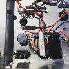
Cleaned out the guts the other night, and the power supply is now overhauled and the EFB circuit in place.
 

Attachments

  • IMG_3623.jpg
    IMG_3623.jpg
    80 KB · Views: 260
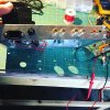
My least favorite part, the metal work, is done. Hopefully he won't ask me to move the power switch and volume control somewhere else :)
 

Attachments

  • IMG_3630.jpg
    IMG_3630.jpg
    90.5 KB · Views: 243
Well, now I'm just waiting for output transformers...
Nice work. I haven't run across one of these amps yet. I have another 175 on the bench waiting on parts. Ive been using Transendar OPT's, but was thinking of trying Edcors this time around. Ill be watching to see how yours turns out.
 
Back
Top Bottom