• The move to the new server is done. There are some software and database maintenance updates in process. This has us passing the hat around to help out. We appreciate any donations. Seriously, even a dollar helps. The payment page may be found here - https://www.audiokarma.org/support.html

Fix that Sansui 9090db with a Bad db board

Lets make one thing clear, their bypass method does not involve removing tape in/out. I said "....And, no functionality loss....".
The ONLY thing bypassed is the DB board.
In light of the above, is it still a hokey kludge that constitutes bad work?
These comments have been due to the AK link on the OP's first post which shows how to bypass the Dolby board on a Sansui 9090db receiver. That thread shows the tape functions have been eliminated with the mod implementation. So...to aid us all, would you be able to share with us how you accomplished this mod while keeping the tape functionality?
 
Lets make one thing clear, their bypass method does not involve removing tape in/out. I said "....And, no functionality loss....".

The ONLY thing bypassed is the DB board.

In light of the above, is it still a hokey kludge that constitutes bad work?

They bypassed the board on my 9090db and I did take pics of it but they got deleted and I no longer have them to share. I wish I could explain and show how they do it, but unfortunately, I can't. I have since modded my 9090db to my taste (see pics above) so photographing my device won't help here either....sigh. But I can tell you it involves jumper wires, it works and the tape in/out still functions.
Then the mods done on yours are different than all of the other Dolby board bypass mod in the OP, and the others that have been proffered up here over the years. It would require manually rewiring all of the tape ins/outs in order to bypass that board and retain their function. I'd love to know more.
The Dolby NR function is bypassed by the switch when it is selected off, but all of the line level signal still passes through F2654 and F2655.
 
I was hoping to find a thread by Trnsfmr detailing the bypass of the Dolby board, but was unable to locate any. I only found one mention where he talks of 9090 have the same issues as the QRX9001.
 
I was hoping to find a thread by Trnsfmr detailing the bypass of the Dolby board, but was unable to locate any. I only found one mention where he talks of 9090 have the same issues as the QRX9001.
He talks about pinning the vias (pass throughs) in that post, which is the standard fix and has been for as long as I've been doing this.
 
Then the mods done on yours are different than all of the other Dolby board bypass mod in the OP, and the others that have been proffered up here over the years. It would require manually rewiring all of the tape ins/outs in order to bypass that board and retain their function. I'd love to know more.
The Dolby NR function is bypassed by the switch when it is selected off, but all of the line level signal still passes through F2654 and F2655.
The task of manual re-wiring of the tape ins/outs is the reason most settle on re-pinning the board. Which is why I'm interested in seeing what @z-adamson has to share with us. It's possible it could forever alter the way we repair the Dolby board.
 
The task of manual re-wiring of the tape ins/outs is the reason most settle on re-pinning the board. Which is why I'm interested in seeing what @z-adamson has to share with us. It's possible it could forever alter the way we repair the Dolby board.
Unfortunately the fellow who did the work is no longer with us. I wasn't being facetious when I said I would love to know more. Based on the one post we have, I would guess that what was done to z's unit was the standard pin and solder, along with maybe a permanent disabling of the Dolby function itself. But that's only a guess.
 
I was hoping to find a thread by Trnsfmr detailing the bypass of the Dolby board, but was unable to locate any. I only found one mention where he talks of 9090 have the same issues as the QRX9001.
From the QRX restore site....

"For more on the 9090, go here. With the DB versions, there is often a problem in the Dolby section, causing intermittent channel dropouts. We disable the Dolby section by bypassing completely. It’s a complicated fix, as the tape ins/outs have to be essentially rewired, out of the dolby circuitry, in order to still be available. We have become quite experienced with this series...."
 
The task of manual re-wiring of the tape ins/outs is the reason most settle on re-pinning the board. Which is why I'm interested in seeing what @z-adamson has to share with us. It's possible it could forever alter the way we repair the Dolby board.
I explained earlier in this thread...


"They bypassed the board on my 9090db and I did take pics of it but they got deleted and I no longer have them to share. I wish I could explain and show how they do it, but unfortunately, I can't. I have since modded my 9090db to my taste (see pics above) so photographing my device won't help here either....sigh. But I can tell you it involves jumper wires, it works and the tape in/out still functions."

QRX restore did the work about 6 years ago. I redid it again a couple years ago. I don't have pics of what qrxrestore did sadly…
 
Last edited:
So we're back to square one, short of reverse-engineering your 9090db or hoping QRX Restore would graciously offer up the modification schematic. facepalm-smiley-emoticon.gif
 
Well here we go... as clarification for newbies that might read this thread.

First of all one thing is a 9090 and other is a 9090DB.

They are very different.

The 9090 is a quasi-complementary amplifier with a different power supply.
It uses a F-2436 board mounted on a F-2546 power supply board.
It is not related to the QRX9001 at all.

9090DB, is complementary design that uses F-2624 boards mounted on a F-2657 power supply board. The only similarity with the QRX9001 is that the 9001 uses two F-2624 boards.

The dolby board used on the x0x0DB, F-2655.

./ It uses a early implementation of vias that with the age develop cracked solders.
Solution: reflow or even better put a pin on the vias and resolder.

./ Early versions uses a green connector ribbon cable that can break, later versions uses a black one more robust.
Solution: Get a ribbon cable (somewhere here in Audiokarma is the Mouser part number).

./ Switch get dirty.
Solution: Clean it.

IMO, the whole thing is overblow out of proportion, those steps will ensure that board function very well, there's no need to bypass, reverse engineer anything, just need some work specially IF the goal is preserve a nice piece of history. Is very basic stuff, just need to be able to block the noise around this board, and go step by step.
 
Last edited:
IMO, the whole thing is overblow out of proportion, those steps will ensure that board function very well, there's no need to bypass, reverse engineer anything, just need some work specially IF the goal is preserve a nice piece of history. Is very basic stuff, just need to be able to block the noise around this board, and go step by step.
Basic stuff for some is brain surgery for others. My first foray into repairing the 9090db Dolby board years ago ended unsuccessfully, as the problem reared it's ugly head a few months after the re-pin. The only thing stopping me from bypassing the board was the fact that it would disable the tape functions, which I use.
So I opened her back up and reflowed the via solder and got her back to working again.
 
To my knowledge, the boys up at QRX Restore have never published their comprehensive Dolby bypass and they are the only ones to claim to do it.

- Pete
 
Hi all, I looked at this issue recently as I have an 8080DB (although that works fine), and it was a bit of a 'puzzle challenge' :)

I looked at the schematics, the F-2655 board already has a bypass function, position 3 on the dolby selector knob.
If that doesn't perfectly bypass it, then there is a fault with either the selector switch (the signal goes through it 3 times) or the ribbon wires have cracked, or the tape monitor 1 or 2 are faulty. Or a combination.

As for the actual bypass, if for some reason cleaning the switch or replacing the ribbon is not the favoured approach - it can be fairly easily bypassed from the parent F-2654 board, without touching the F-2655 board, that can stay in there safely preserved.

The pin numbering of the ribbon is amusingly 'non-sequential', and the service manual has some errors, which may make the task of computing a bypass seem tricky, but once the correct S01 switch elements are identified, along with the correct ribbon pins, the task is straightforward.

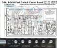
- Simply remove all the ribbons, then on the F-2654 use 4 jumper wires in place of the ribbon (to emulate the dolby 'off' position), and then unsolder the f/g blue and grey signal input wires from the F-2655 daughter board, and solder them instead straight to the F-2654 board.
That's it.

ETA:
If you look carefully at my attached image, you can trace the signal as it arrives at pins 1 and 2, into the Tape Record out 1 (TR1) and Tape Monitor 1 switch, the switch selects source or Tape Play 1 (TP1), then goes to TR2 and tape monitor 2 switch for TP2, then via pins 23 and 24 goes to the mono, loudness etc and then out of 33 and 34 to the tone board.
I.e. my bypass method here is simple and gives the full tape loop functionality of the original.
I.e. this is the solution everyone has been looking for :)

Doing this, (in theory, I've not done this to mine as it works), gives the behaviour of 'dolby Off', without any signal touching the F-2655 board.
I post the image I made as I worked it out for anyone who is interested - I don't think bypassing is the best fix, but at least my method preserves the F-2655 board for the future, and allows the tape loops to work as in the original) so it's Ok I guess :D

If anyone does this bypass, please post up how it works for them :)

 

Attachments

  • F-2654 Push Switch Circuit Board PCB + FPanel.jpg
    F-2654 Push Switch Circuit Board PCB + FPanel.jpg
    209.5 KB · Views: 137
Last edited:
Hi all, I looked at this issue recently as I have an 8080DB (although that works fine), and it was a bit of a 'puzzle challenge' :)

I looked at the schematics, the F-2655 board already has a bypass function, position 3 on the dolby selector knob.
If that doesn't perfectly bypass it, then there is a fault with either the selector switch (the signal goes through it 3 times) or the ribbon wires have cracked, or the tape monitor 1 or 2 are faulty. Or a combination.

As for the actual bypass, if for some reason cleaning the switch or replacing the ribbon is not the favoured approach - it can be fairly easily bypassed from the parent F-2654 board, without touching the F-2655 board, that can stay in there safely preserved.

The pin numbering of the ribbon is amusingly 'non-sequential', and the service manual has some errors, which may make the task of computing a bypass seem tricky, but once the correct S01 switch elements are identified, along with the correct ribbon pins, the task is straightforward.

- Simply remove all the ribbons, then on the F-2654 use 4 jumper wires in place of the ribbon (to emulate the dolby 'off' position), and then unsolder the f/g blue and grey signal input wires from the F-2655 daughter board, and solder them instead straight to the F-2654 board.
That's it.

Doing this, (in theory, I've not done this to mine as it works), gives the behaviour of 'dolby Off', without any signal touching the F-2655 board.
I post the image I made as I worked it out for anyone who is interested - I don't think bypassing is the best fix, but at least my method preserves the F-2655 board for the future, and allows the tape loops to work as in the original) so it's Ok I guess :D

If anyone does this bypass, please post up how it works for them :)
Does this make tape function not work though?
 
Do you need to use shielded wire to make those jumpers?
No, the F-2654 PCB has no ground plane, and all the ribbon wires were just hanging in the air, so I would just use some convenient wire to hand, perhaps a different colour for each channel (as per red and blue above).

The grey and blue fly leads (incoming signal from the main selector switch) that need to be removed from the F-2655 dolby board and soldered to the pin 1 and 2 on the F-2654 switch board will need their ground connecting to 705 as shown in the diagram.

That ground meanders all over the place in the ribbon and F-2655 so just make it neat, don't worry about the shielding, Sansiu didn't and all was fine :)

My bypass is actually very straighforward - relocate the input signal (grey and blue shielded wires from the main selector) to pins 1 and 2 (which is where 'dolby off' sends them), one pair of jumpers bypasses one bit of the dolby board (emulating one of the dolby-off switch - the 2nd pair of jumpers does the same for a different part of the dolby off switch, and then the signal wriggles through the mono and loudness buttons and out to the level and balance as before.

The reason people didn't solve it before is simple: The diagram and numbering was very confusing, as is the switch designations, all switches are S01, but each used toggle is lettered a,b,c etc. Once identified, the bypass is obvious - but without that first step, it's very complex :D
 
No, the F-2654 PCB has no ground plane, and all the ribbon wires were just hanging in the air, so I would just use some convenient wire to hand, perhaps a different colour for each channel (as per red and blue above).

The grey and blue fly leads (incoming signal from the main selector switch) that need to be removed from the F-2655 dolby board and soldered to the pin 1 and 2 on the F-2654 switch board will need their ground connecting to 705 as shown in the diagram.

That ground meanders all over the place in the ribbon and F-2655 so just make it neat, don't worry about the shielding, Sansiu didn't and all was fine :)

My bypass is actually very straighforward - relocate the input signal (grey and blue shielded wires from the main selector) to pins 1 and 2 (which is where 'dolby off' sends them), one pair of jumpers bypasses one bit of the dolby board (emulating one of the dolby-off switch - the 2nd pair of jumpers does the same for a different part of the dolby off switch, and then the signal wriggles through the mono and loudness buttons and out to the level and balance as before.

The reason people didn't solve it before is simple: The diagram and numbering was very confusing, as is the switch designations, all switches are S01, but each used toggle is lettered a,b,c etc. Once identified, the bypass is obvious - but without that first step, it's very complex :D
This is awesome!!! Thank you.
 
I really want to try this bypass. It's a real breakthrough.

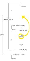
Here is CDFixer's Dolby Switch schematic and a separate correction to it. It's a big improvement to the service manual schematic. He posted it somewhere while he was still around. He used this guide to find and repair bad pass throughs.

- Pete
 

Attachments

Back
Top Bottom